If you are driving an inductive or motor load you will need flyback or freewheel diodes across all mosfets. In order to bias these mosfets in the active region a voltage must be applied to the gate that meets the v gs(th) value as specified in that particular mosfets data sheet. The proposed technique is a simple improvement to the gate driver based on the ir2112 driver (ic) by adding a capacitor to attenuate the effect of parasitic components and the freewheeling current, suppressing the negative.
MOSFET based Hbridge dcac inverter. Download
Mosfet, bjt, ijbt, or thyristor, etc.
This simple yet effective setup is very useful in inverter applications where we need to convert high voltage dc to 50 or 60 hertz ac signal that can be used to drive out ac loads.
Pcb area footprint by 50%, component count and pcb area, and overall cost. Electronics 2021, 10, 390 3 of 17 figure 1. It is the simple and elegant solution to all motor driving problems. The mosfets are used as switches and are activated in diagonal pairs.
Based on the above schematics simply switch motor voltage off, change direction, then motor voltage back on.
This type of motor driver can control the speed as well as the direction of rotation of the motor. The mosfet or igbt is used for switching purpose. In a typical h bridge configuration as shown in figure 2 there are two high side mosfets, each located on opposite sides of the bridge. Control switch can be any electronic switch i.e.
The diodes d1 to d4 provides a safer path for the back emf from the motor.
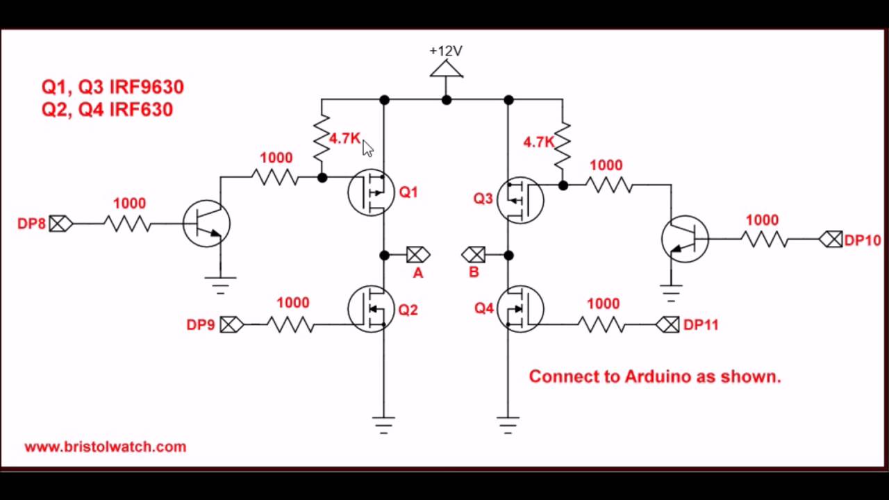
Current flowing through the lower resistor from the capacitor will make the voltage at the upper inverter's input fall slower, so there will be a delay before signal a goes high. In the circuit, we see that the 4 mosfet surrounding the motor form an “h” shape. H bridge consists of four switches. Mosfet based h‐bridge dc‐ac inverter.
This type of inverter requires two power electronics switches (mosfet).
Circuit diagram of the half bridge inverter is as shown in below figure. An h bridge is an electrical circuit that changes the polarity of an applied voltage to a charge. I have built the circuit attached herein on a pcb. A 'high' turns on q7 driving its collector 'low' and through cd4011b being used as an inverter produces a 'high' on the gate of q5.
And the output of the 12v supply that i used to power the vcc pin of the ir2110 gets messed up as well.
These switches can be transistor, thyristors, and mosfets. I have used mosfets in h bridge designing for pure sine wave inverter. But when i try to combine them the ir2110 always blows up. As shown in circuit diagram, input dc voltage is.
Pcb area footprint by 50%, component count and pcb area, and overall cost.
Thus it protects the corresponding mosfet from damage. Two power switches in a complementary manner are used in Proposed technique in power switching applications, switching losses at most are dependent on switch‐ The direction can be changed easily and the speed can be controlled.
Such h bridge is quite common in relatively cheap modified square wave inverters though this can also be used in pure sine wave inverters with appropriate modifications.
These circuits are often used in robotics and other applications to allow dc motors to run in or out. The performance of the proposed technique has been evaluated experimentally. I have used irf840 mosfet in h bridge due to its high current and voltage handling capability.you can check its data sheet for more information about it.