It is hard to find equipment. The backup battery will take up the load with no spikes or delay when the mains electrical power gets interrupted. Here the simple mini ups circuit diagram.
1.5v to 220v Inverter Electronic circuit projects
If you think that this circuit is not good enough.
The output frequency at ic1 will be determined from r1 and c1.
We have used easyeda to draw this circuit diagram, and covered a tutorial on ‘ how to use easyeda for drawing and simulating the circuits ’. 18w mini inverter (12v dc to 220v ac) it is a premium quality 18w mini inverter circuit pcb board suitable for led bulbs, cfl, mobile charging, home made mini diy inverter, etc. Inverter circuit diagram with parts list. Dc/ac pure sine wave inverter jim doucet dan eggleston jeremy shaw mqp terms abc 20062007 advisor:
So, if both values error frequency will cause the frequency output to wrong.
The square wave is fed to ic 4017 which will convert to modified sine wave at 50hz at 50% duty cycle. Mini power inverter schematic circuit diagram. Also 500w inverter circuit for you. Battery level indicator & inverter circuit.
In a power loss situation, it will supply power from the onboard battery supply.
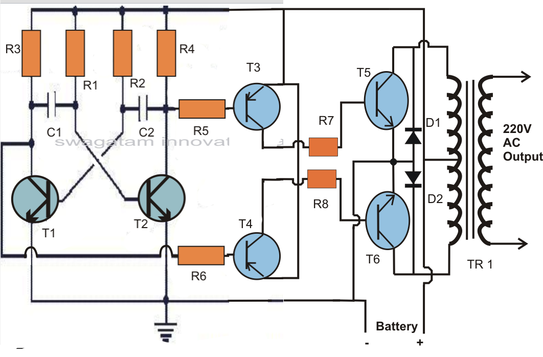
Inverter circuits are among the easiest circuits to build for newbies. Mini inverter typical wiring diagrams emergency lighting central inverter systems. The circuit is simple low cost and can be even assembled on a veroboard. 100 watt inverter circuit diagram.
Circuit diagram of 100 watt dc to ac inverter has been given below.
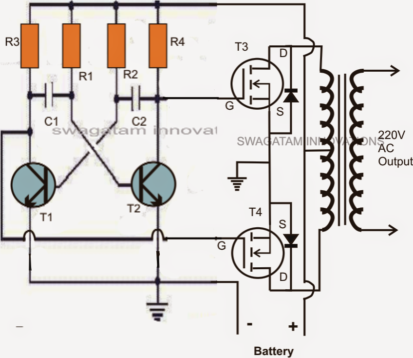
You can also covert this circuit diagram into pcb layout, as we have explained in easyeda tutorial, and build this project on pcb. This inverter circuit can easily convert the input 12v battery power to output 220v ac (up to 18 watt) where the size of the inverter is small, working with heat sink. Save these instructions the installation and use of this product must comply with all national, federal, state, municipal or local codes that apply. The q and q outputs of ic2 directly drive power mosfets (t3 and t4).
Drill/make suitable holes to enable easy and firmed fitment on the cabinet of the inverter.
Modified sine wave inverter circuit diagram the circuit consists of ic 555 which is tuned to generate frequency at 200hz (square wave) at 50% duty cycle. The inverter is built around ic2 , which is wired as an astable multivibrator operating at a frequency of around 50 hz. Scheme inverter circuit is capable of removing power. The inverter output is filtered by capacitor c1.
Drill holes for fitting the power transistors.
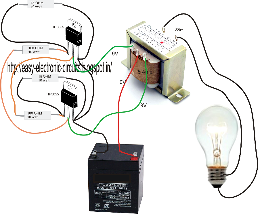
This inverter circuit diagram which can change the voltage 12 volt dc to 230 volt ac. The holes should be approximately 3mm in diameter. A 12 v car battery can be used as the 12v source. Diy cheap 1000w pure sine wave inverter (12v to 110v/220v):
Even robot systems occasionally need a negative supply voltage for some purpose or other, and in this kind of application, in particular, there is a need for an effective circuit that does not make greater demands then necessary in terms of current or space.
Car batteries for powering you home? Use the pot r1 to set the output frequency to50hz. There are many basic electrical circuits for the power. The mini inverter works in conjunction with incandescent, led, and
The diy inverter board can handle up to 1kw (depending the transfor…
Take an aluminium sheet and make/cut the sheet into two parts of nearly 5×5 inch. They can convert 12vdc from battery to 220vac or 120vac to apply small light bulbs or lamps max 10 watts. The project is based on the low cost egs002 spwm driver board module. In the two circuit diagram below, just use 2 transistor, 2 resistors, and one transformer only.
Which is an output pin of ic1 by both signals will have status always opposed.
By continuing to use this website, you consent to cookies being used.