Sine wave inverter circuit using pic16f72. Sine wave inverter circuit diagram with complete step by step program and coding, in this article i will discuss how to use push pull converter, sinusoidal pulse width modulation, h bridge and low pass lc filter to make pure sine wave inverter circuit diagram. 12v dc to 220/230v ac homemade 500w inverter circuit.
Microtek Inverter 800Va Circuit Diagram Pdf Sine Wave
The square wave is fed to ic 4017 which will convert to modified sine wave at 50hz at.
Op amp 2 as an inverter.
Please reset the circuit breaker, or if the fuse is blown, replace it with 10amp rating fuse. High power homemade inverter circuit diagram. 1500w inverter full schematics and pcb.rar: 1kva 1000 watts pure sine wave inverter circuit electrical engineering world electronic circuit projects circuit diagram electronic circuit.
Mosfet used as a switches in push pull operated through control circuit in such a
Sukam sinewave inverter diagram smd and old and microcontroller pin details with falut finding youtube from i.ytimg.com 800va pure sine wave inverter's reference design 7. I have already discuss all these topics in following articles.i suggest you to go. 800va pure sine wave inverter's reference design 7. Sine wave inverter circuit description.
Microtek inverter circuit diagram pdf electrical learner.
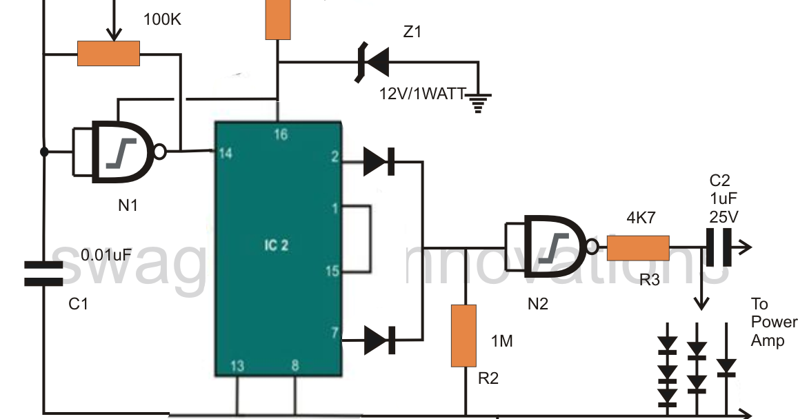
If circuit breaker trips or fuse blows again, call electrician to check shorting in the load wiring. The icl7660 or max1044 can be selected. Two ic used in this circuit. The circuit consists of ic 555 which is tuned to generate frequency at 200hz (square wave) at 50% duty cycle.
I want to tell you that pure sine wave inverter schematic.
Microtek inverter low battery, overload, mains changeover, relay drive volt, mosfet drive volt full hd diagram. 2.ups trips frequently at backup mode. 3 phase inverter circuit diagram the internet is flooded with single phase inverter circuit diagrams but there are only few circuit diagrams of 3 phase inverter out there. Last updated on august 3, 2020 by swagatam 241 comments.
Modified sine wave inverter circuit diagram.
Buy best inverter for home, office & shops at best price. It passes the high dc voltage for specified amounts of time so that the average power and rms voltage are the same as if it were a sine wave. Connection of transformer must be reversed. Modified sine wave, and pure sine wave1.
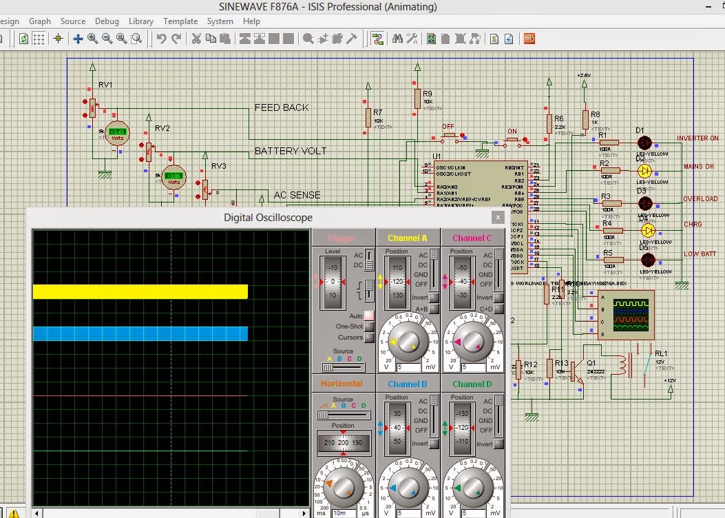
The following image shows the complete circuit diagram of the sinewave inverter, the images are divided into two in order to fit inside the page, please join them together after.
Make this 1kva (1000 watts) pure sine wave inverter circuit. Simple modified sine wave inverter circuit. How to build 200w inverter circuit diagram project eleccircuit com. Read online inverter circuit with pic16f72 microcontroller and push pull topology.
Ups inverter diagrams pdf free 3000w power 12v to 230v digital circuit diagram 4 simple uninterruptible supply sinewave using pic16f72 homemade solar m 100 watt offline engineering projects electronic abc home facebook sine wave build 200w 500 with battery circuits 2000w homage schematic microtek how an works.
A modified sine wave can be seen as more of a square wave than a sine wave; Microtek offers home inverter, high power inverter, voltage stabilizer & solar. A relatively simple 1000 watt pure sine wave inverter circuit is explained here using a signal amplifier and a power transformer. Multivibrator cd4047 and opamp comparator lm324 , 6 power transistors are used to make high load capacity inverter.
Download sukam sine wave inverter circuit diagram 800va pics.pic codes can be viewed here.
The post details comprehensively regarding how to build a pure sinewave inverter circuit using microcontroller circuit with pic16f72. First with a double voltage module voltage for the op amp power supply. Digital inverter circuit diagram ac converter 100 watt cd4047be 100w china electrical engineering solar luminous 12 volt 1000 power design 172 173 model 875va original fake dc control board feiya 94v0 pcb 500 watts to make your own sine wave full esp motherboard 300 for the lg ltnc11121v high frequency. Modified sine wave inverter circuit diy electronics projects.
Microtek sine wave inverter full circuit diagram.
Microtek 850va and 1100 seb sine wave inverter circuit diagram. Op amp 1 generates a 50 hz sine wave as the reference signal. As can be seen in the first diagram below, the configuration is a simple mosfet based designed for amplifying. It comprises a cd4047 multivibrator (ic1), irf250 mosfets (t1 through t8), transistors and a few discrete components.