The following circuit diagram is for 110v operation (article has instruction for modifications for 220v operation). Hopefully those looking for practical information on electrical circuits and wiring led components found this guide first. Fluorescent ballasts can fail, requiring continued maintenance and eventual replacement or.
Led Fluorescent Tube Replacement Wiring Diagram Download
An led tube light is an led retrofit lamp that serves as a replacement light source for linear fluorescent lamps.
3 volt basic led circuit with 10 ohms resistor.
The voltage drop across an led is approximately constant over a wide range of operating current; It is electromagnetic ballast or electronic ballast. Therefore, a small increase in. Once the gas in tube ionized means then current flow occurs and tube will start continuous glowing.
The total electrical components for single tube light installation are.
Philips t8 led tube tear down: It’s likely though, you’ve already read the wikipedia page about series and parallel circuits here, maybe a few other google search results on the subject and are still unclear or wanting more specific information as it pertains to leds. Although it operates at 230 v, 50 hz, some auxiliary electrical components are used to insert in this installation to support the tube light operational principle. As a product developed to address the needs of retrofitting.
As we all know led tube light and led bulbs are very famous now a days.
Hi , i take out the led strip from one of the led tubelight which stopped working. T8 led tube lights:typically found for general lighting applications in offices and warehouses, t8 tube lights are the most common type of tube light available. In this circuit, we will drive an led directly from 230v ac mains supply. This kind of tube light is a row of led’s which runs on 110 or 220 volts ac, just like your ordinary fluorescent tube light.
1) the specified voltage of the leds and components used, and.
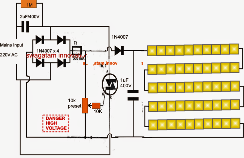
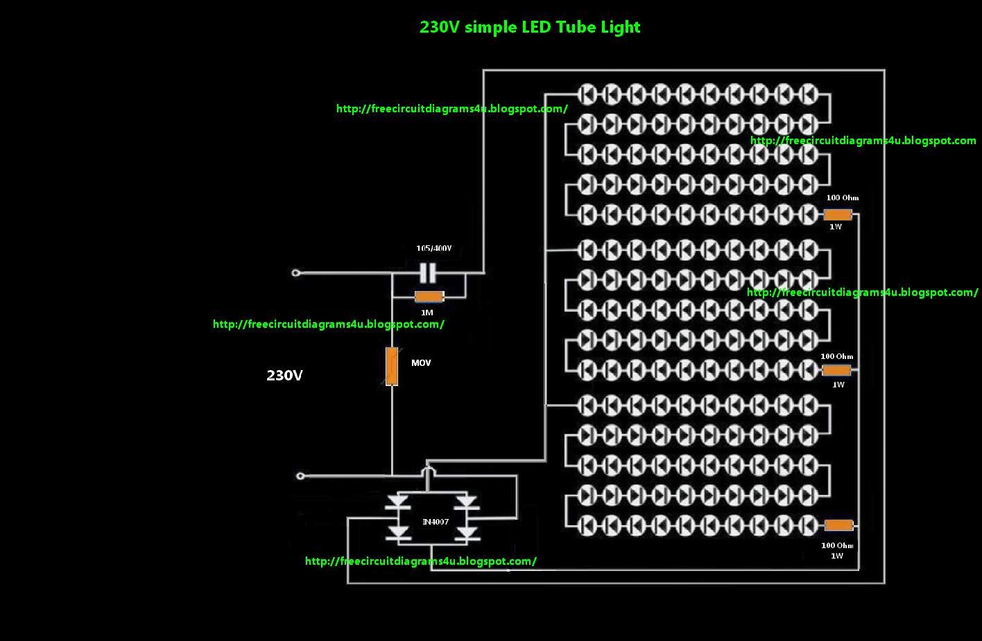
A wiring diagram is a simplified standard pictorial representation of an electrical circuit. Led tubes are designed to fit into the fluorescent sockets, effectively converting the light fixtures that originally accommodate fluorescent tubes into more energy efficient, longer life led systems. 230 volt ac direct led tube light driver circuit designed with few easily available components. 230v led tube light circuit diagram.
Government also motivates us to use led tube light and bulb in our daily life.
The 3 segments should be connected in parallel to the house ac outlet. This circuit can be build as 20 watt or 10 watt white led tube light. Transformerless 110v tube light circuit. Your tube light is ready.
1 the specified voltage of the leds and components used and.
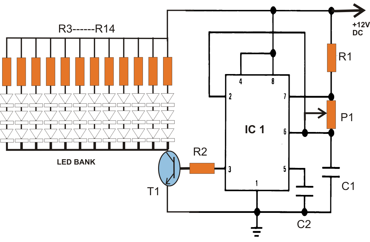
I have checked each led on the strip and every led is good to go. The circuit utilizes 30 numbers of 1 watt leds, as well as contains a voltage and current control capabilities. Led tube light ac led tubes led tube light electronic circuit projects The gap between the led's should be 1 inch so as to cover the 4 feet of pvc batten.
The above diagram shows a 3v led circuit, in this circuit there are two aa cells are used.
When you are operating an led with 3v you have to use minimum 10 ohms resistor. Another interesting led circuit is the diy led light bulb. Led tube light driver circuit. It is very dangerous to use 230v ac supply on breadboard.
Led tube light (ac) article tells how to make a led tube light.
2) the configuration of the leds on the led strip. A tube light is not connected in the supply main directly. The post describes a basic single ic led tube ligt circuit relevant for 110v/120v ac inputs. Follow the circuit diagram in detail.
An led tube light is lighting device built using high efficiency leds for illuminating a premise where it is installed through the available ac mains supply.
In this, we designed an led light bulb and used it as a regular bulb. Switch it on and enjoy the soft light. Here is a 23v0v led driver circuit. It includes guidelines and diagrams for different varieties of wiring techniques and other items like lights, windows, etc.