Led driver changes the power supply to a specific voltage current to drive the led voltage converter. A wiring diagram is a simplified standard pictorial representation of an electrical circuit. Follow the circuit diagram in detail.
230V AC Blinking LED Circuit
3 volt strobe light, dc strobe light, mini strobe light, strobe light circuit led indicator for 220v ac mains this is the schematic diagram of led indicator for 220v ac mains which can be used to indicate that the cable.
Or you can make one using components like an inverter a 555 timer or a microcontroller.
In this circuit, we will try to connect three 5mm white leds in parallel and light them up using a 12v supply. 230v ac led driver circuit for powering 2.5watts led light. 110v compact led tubelight circuit. In my previous post i discussed the ic tl783 which is a 1.25v to 120v variable dc regulator ic.
Two lamps connected in series circuit diagram stock image c050 8158 science photo library.
The resistor r1 controls the amount of current going through the led. Circuit and 11watts tube the led light is much better the layout is made in such a way you get uniform illumination a photograph of the cicuit. This circuit can be build as 20 watt or 10 watt white led tube light. The above diagram shows a 3v led circuit, in this circuit there are two aa cells are used.
220v ac led light circuit diagram.
The circuit diagram for leds in parallel connection is shown in the following image. This circuit is made with few numbers of parts namely, a led, two resistors, one capacitor, one diode and one diac.the diac act the main role to flashing the led. 12v led light circuit […] Cut back additional wiring on opposite side of ballast as the led tube lamp only requires power at one end.
I am sending you a table lamp made from defunct energy saver lamp with broken tubes.
Carefully remove the broken glasses. The 3 segments should be connected in parallel to the house ac outlet. Direct cur circuit diagram with light bulb on stock ilration 55296570 pixta. It’s likely though, you’ve already read the wikipedia page about series and parallel circuits here, maybe a few other google search results on the subject and are still unclear or wanting more specific information as it pertains to leds.
Seetharaman’s words about the circuit:
Naep science 2009 grade 4 electrical circuits hands on task hot administration and scoring materials. Simple diagram for led lamp house.using transistor d 613, h1061, or c945, c1815105 or. This is a very simple led flasher circuit diagram that is powered from ac 230v mains. The circuit looks pretty simple.
Another interesting led circuit is the diy led light bulb.
Few components available in the cfl pcb also can be used. Ac led driver circuits are overly popular due to the advancement of high current white leds. Circuit 3 of simple led circuits (leds in parallel) the final circuit in the simple led circuits tutorial is leds in parallel. 1 the specified voltage of the leds and components used and.
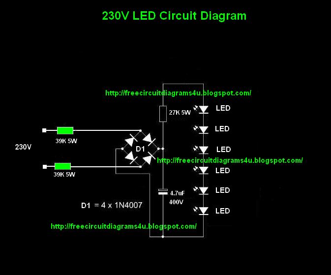
Simple and low cost solution for lighting is ac powered 230v led circuit, here the high bright white leds are connected to the ac power source with the help of few rectification components without any stepdown transformers.
Remove the ballast from the You also need to make a large number of clean connections using delicate parts as opposed to. Hopefully those looking for practical information on electrical circuits and wiring led components found this guide first. When you are operating an led with 3v you have to use minimum 10 ohms resistor.
I led driver basics 1.
The downside of this kind of design is the power loss by the current limiting resistor and the fact that the light output flickers at 100 hz frequency. The article explains a simple single ic led tube ligt circuit applicable for 110v/120v ac inputs. Most of the components will be available in ones scrap box. Cfl converted into led lamp.
12 volt led light strips.
1 what is a led driver. Your tube light is ready. Pin on technology the circuit inside the unit regulates the ac voltage coming from the generator to 135 14 vac for the bulbs. The circuit uses 30 numbers of 1 watt leds, and also includes a voltage and current control features.
3 volt basic led circuit with 10 ohms resistor.
Led light tube circuit diagram gives a quite simple looking circuit diagram for a 230v mains powered led tube: 230v led tube light circuit diagram. We already made a transformerless led driver circuit previously, but in that circuit, we used a dedicated led driver ic like lnk304 to generate 13.6v 150ma of output current to power leds. 230 volt ac direct led tube light driver circuit designed with few easily available components.
Fix 3 segments of 90 led's as shown in the photographs.
How to make led light lamp your own. Hence the cost of this circuit may few bucks and the output light worth few dollars. The gap between the led's should be 1 inch so as to cover the 4 feet of pvc batten.


