Once the magnet is brought near the vicinity of the circuit, it will turn off and the led will be turned off. It’s likely though, you’ve already read the wikipedia page about series and parallel circuits here, maybe a few other google search results on the subject and are still unclear or wanting more specific information as it pertains to leds. I led is the desired current through the led.
InWall LED Dimmer Switch
By soft touch, it means that one has to push the button once to set the device on and push again to set the device off.
With the switch open, you have about 11 ma base current into the bjt.
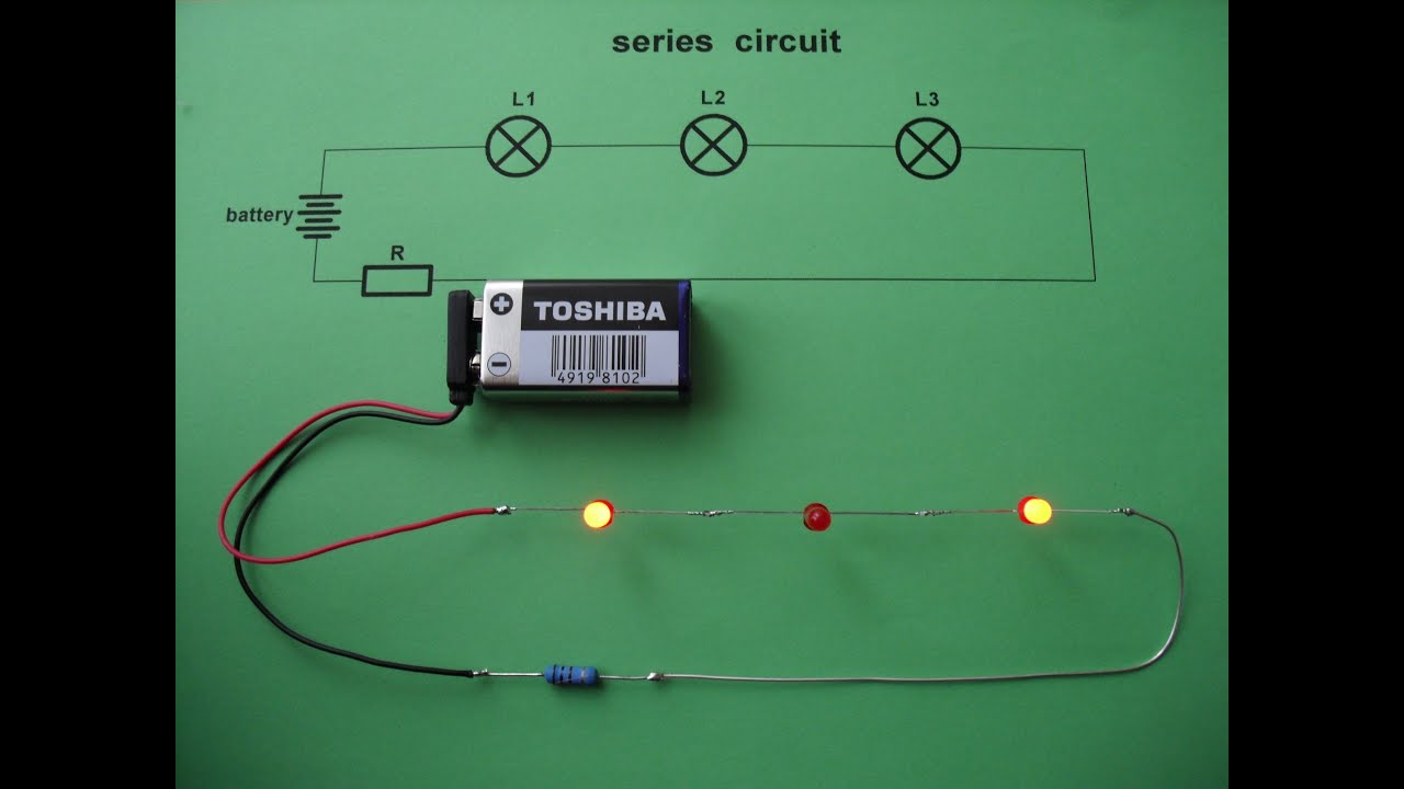
This circuit is a simple series circuit to power three leds. An led driver is an electronic circuit that utilises a transistor to switch power to an led. If the led has a higher power requirement, then it. This switch comes in both toggle and rocker variants.
The circuit used is a 5mm led in series with a 330ω 1/4w resistor.
The above diagram shows a 3v led circuit, in this circuit there are two aa cells are used. V1 = i*r1 + vf. That process repeats to the next led until it reaches the end. The mosfet (metal oxide semiconductor field effect transistor) is a semiconductor device that is widely used for amplifying and switching electronic signals.
In your case the supply_voltage is 9 volts.
Normally the resistance of an ldr is very high, sometimes as high as 1000 000 ohms, but when they are illuminated with light. Here are some diy ldr switch circuits available on our website and the web. /* button turns on and off a light emitting diode(led) connected to digital pin 13, when pressing a pushbutton attached to pin 2. Where using arduino programming and basic circuit diagram.
In this case, the 2 most important parameters are the current and the voltage.
Hopefully those looking for practical information on electrical circuits and wiring led components found this guide first. The switch is the double pole double throw. To be on the safe side, use the next higher resistor value of 390 ohms. Ldr switches are used to switch a relay or other device when light are present or absent.
One of the simplest types of led display circuit is the led flasher in which a single led repeatedly switches on and off, usually at a rate of one or two flashes per second.
In this tutorial, we are going to design a soft touch switch circuit. Ldrs or light dependent resistors are very useful especially in light/dark sensor circuits. When you are operating an led with 3v you have to use minimum 10 ohms resistor. Make a led circuit using the potentiometer to control the brightness of a led when you change the position of the potentiometer.
Now, put the battery onto the bottom of tape c.
Before we figure out the appropriate components, let's find out the requirements for the circuit to work properly. With a normally closed reed switch, the circuit will be on without a magnet, so the led will be lit. Switch state is communicated to the user in real time due to the illumination, helping to energize any design. On most arduinos there is already an led on the board attached to pin 13.
The series wired led circuit.
Meanwhile, a complex circuit will often incorporate a microcontroller. The led_current can be 20 ma. 1 a through the bjt collector, with about 9 v v ce means about 9 w of heat generated in the transistor. With a typical gain of 100, this means you are trying to pull 1 a through the led and through the bjt's collector.
And this demonstrates the operation of a reed switch.
If your led is not rated for 1 a, it's most likely a goner. The resistor is required to properly power the lamp. Usually, the signal from a microcontroller, or logic gate, does not possess sufficient drive current to power an led directly. You'll note two main differences between this and the parallel circuit.
The m2100 series is unique because it has both isolated and synchronous led control operations which grants maximum flexibility for design.
As per the datasheet of the 5mm white led, the forward voltage of the led is 3.6v and the forward current of the led is 30ma. Assuming the led's forward voltage is 2v, forward current is 20ma, the calculation for the resistor is as following: Substituting these values in the. The circuit for switching the parameters needed.
The red led will have a led_voltage of about 2 volts.
When the switch is off (open, like displayed in the schematic), the voltage source provides current to the led through the resistor, so it turns it on. Then, fold the card halfway between tape a and the other two. Therefore, v s = 12v, v led = 3.6v and i led = 30ma. The high voltage on the output port “led” will cause a voltage drop between.
It controls the led light’s switch timing and cycle.
This is because, in the saturation region, there is a constant. When you slide the switch to the on position, a high voltage will be placed on fpga pin t10, which is mapped to the input port of the circuit “led_sw.” the digital circuit then transmits the signal onto the output port led, which is connected to fpga pin u16. If the voltage is reversed and exceeds the reversed voltage (vr), the led can be damaged. Once the forward voltage (vf) and current (if) are achieved, the led will illuminate.
In our simple led circuit consisting of a single led, we have used a 5mm white led and a power supply of 12v.
Typically, a basic circuit utilizes a 555 ic and 1407 ic controller to produce a pulsing light effect. If the led doesn't light up, flip the battery over.