In our simple led circuit consisting of a single led, we have used a 5mm white led and a power supply of 12v. Any holes drilled into sign cabinet must be sealed. Failure to do so may cause a short and void warranty.
LED Resistor Calculator Inch Calculator
This value will likely be between 1.8 and 3.3 volts.
Another way to tell which lead is the anode and which is the cathode is to look at the two plates at the end of the leads inside the body of the led.
The l (line also known as live or phase) is connected to the first lamp and other lamps are connected through middle wire and the last one wire as. The cathode is marked on the rim of the led body with a flat area shown in the diagram. If playback doesn't begin shortly, try restarting your device. Each lamp is connected to the next one i.e.
If you do not have this value, it can usually be determine used a multimeter diode setting.
This sign is intended to. 1) line/neutral connections can be made to either end of lampholder as shown ‐ not polarity specific 2) please use diagram #1, or diagram #2, or diagram #3, or diagram #4 below. Leds must have a resistor in series to limit the current to a safe value, for testing purposes a 1k resistor is suitable for most leds if your supply voltage is 12v or less. Turn off/on led in any state brightness shortcut button:
Voltage of power input port:
V led is the voltage drop across the led and. Each part ought to be placed and connected with other parts in specific way. Here’s a similar led wiring diagram showing 4 seperate led’s (not connected). Remember to connect the led the correct way round.
Notice the load resistor that is needed for each led.
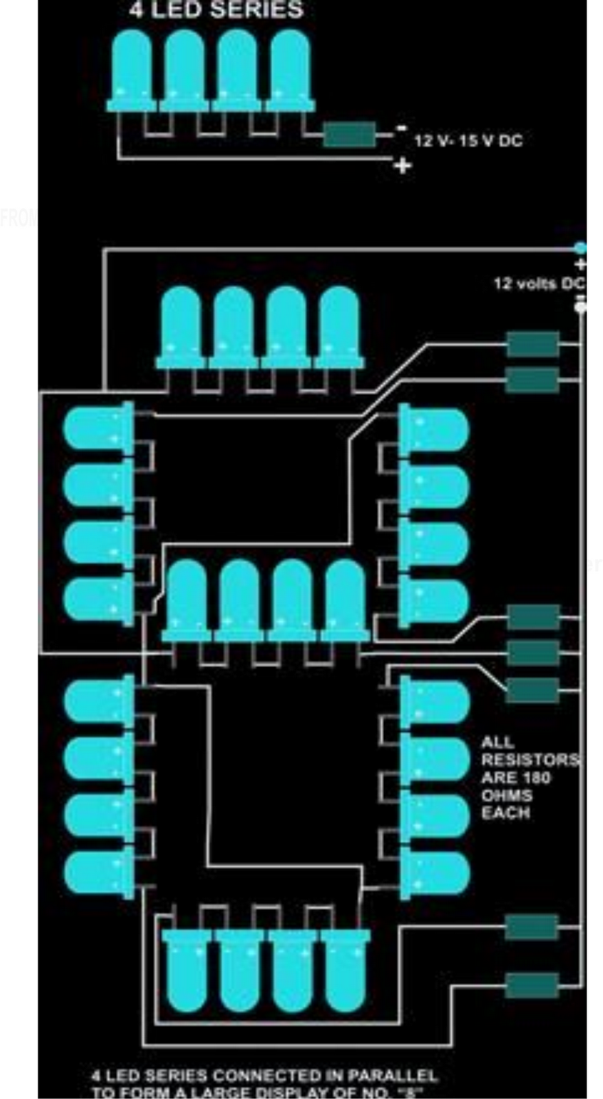
7 led round assembly led series/parallel connection diagram. Sometimes you'll find additional labels: Co 600 top 8 3 4 5 6 7 2 1 pin housing / white (+) vdc / no connection / black / ground or blk/wht / ground (24v) (amp) position 1 position 2 position 3 3 2 1 socket housing (deutsch) position a position b. Videos you watch may be added to the tv's watch history and influence tv recommendations.
Here is the circuit diagram for simple led circuit.
The above diagram shows a 3v led circuit, in this circuit there are two aa cells are used. Dot led series wiring diagram always turn off the power prior to installation. Otherwise, the structure will not work as it. In above fig, all the three light points are connected in series.
The bigger plate will be the cathode.
If you have 3 led cobs, each with a forward voltage of 36v at a given current, when you wire them in series, the total voltage drop of the circuit. On schematic diagrams, its symbol is similar to the simple diode, with two arrows pointing outwards. I led is the desired current through the led. On the physical led, the longer lead (or leg) of the led is the anode.
12/24vdc power output for connecting leds
All wiring diagrams will work with the 1 source led tl series led tube light. Also notice that the anode on the led is connected to positive. #8 x 1 pphsms m4. Maximum or minimum brightness used for getting the brighness between maximum and minimum brightness used for increasing or reducing brightness.
Led color black mounting dimensions 4.20 2.10 0.25 0.625 0.25 wiring diagram to +12v to +12v to +12v wht/vio led color black violet grey sync ground ground 1a fuse 1a fuse 3a fuse 3a fuse sp/st sp/st sp/st mom.
You just need to connect positive terminal of led with the one end of resistor and then connect another end of resistor with the positive terminal of battery. When a series led connection is in question, you will just need to replace the led forward voltage with total forward voltage in the formula, by multiplying fv of each led by the total number of leds in the series. Dot0220 dp general wiring guidelines* number of messages typical wire (lead) colors message 1 black with white stripes message 2 black with yellow stripes message 3 black with red stripes message 4 black with blue stripes message 5 black with gray stripes The value of the series resistor can be calculated using the following formula.
Series wiring is used most often with constant current drivers.
Here, v s is the source or supply voltage. Dot led series wiring diagram always turn off the power prior to installation. When you wire in series, you add the forward voltages of each led in the circuit but the current fed to each led remains the same. 3 volt basic led circuit with 10 ohms resistor.
10% increase or reduction in every step.
Refer to the diagrams shown for mounting measurements specific to your model.whelen series wiring diagram ~ thanks for visiting our site, this is images about whelen series wiring diagram posted by brenda botha in whelen category on nov 12, you can also find other images like wiring diagram, parts diagram, replacement parts. A positive (anode) and a negative (cathode). Never connect an led directly to a battery or power supply because the led is likely to be destroyed by excessive current passing through it. Then connect the negative terminal of led with the negative terminal of battery.
An led has two leads:
When you are operating an led with 3v you have to use minimum 10 ohms resistor. A red led typically has a forward voltage drop of approximately 1.8 volts, increasing to approximately 3.3 volts in a blue led as the colors move through the spectrum. Make appropriate wiring connections per local code. The anode is the longer lead.


.jpg)


