I = current through led. The rated led voltage is subtracted from the voltage source, and then divided by the desired led operating current: Where, v s = source voltage (usually a battery or power supply voltage) v f = led’s forward voltage.
FEELDO 2Pcs HB3/9005 Load Resistor Fog Lamps Decoder LED
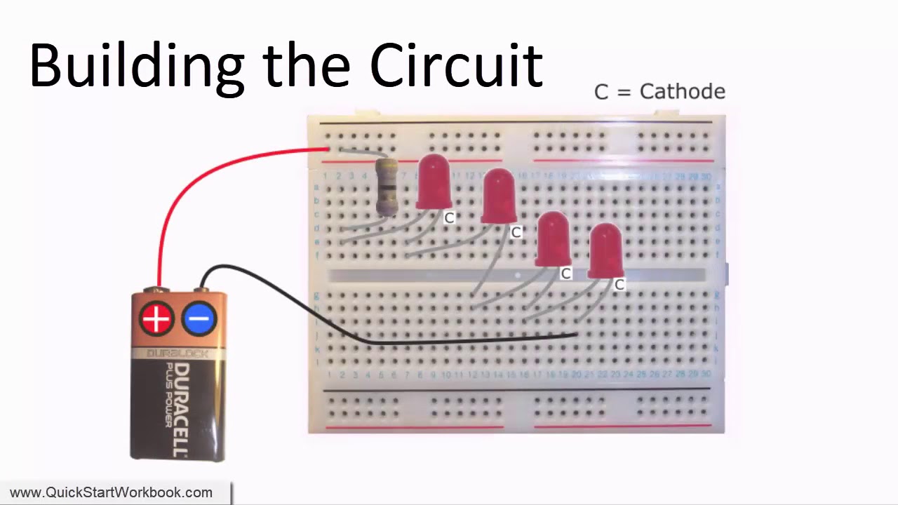
A led has no positive nor negative.
With power off, locate the power and ground wires for the light to which the resistor will be connected do not cut the wires.
R=v/i or, more relevant to what we're doing: Do leds require resistors all of the time? 330 ohms may be used by some people as a. Up on turning on the supply, all the leds will light up.
Leds are diodes which means that current can only flow through an led from the anode to the cathode and not the other way around.
That tuturial is not very good to start. Let’s learn how to find the resistor for leds. After this, you can begin joining the common positive ends of the leds together, and the negative ends or the resistor. This is very straightforward as you need to simply tap the load resistor wires between the two wires.
Thus, applying this law for led circuit, we will get following formula:
For example, you can take two red and blue leds to create the blink project by connecting their positive (long legs) pins to 13 and 12 pins, respectively, through resistance. I would like to connect and power a led directly by using a gpio pin of the esp32 board (i am using the esp32 nodemcu wifi dev kit c). There are some instances where a resistor might not be required when connecting a led to a voltage source. Leds must always be connected in series with a resistor.
There is a little more trial and error involved with the wiring.
The resistor gets extremely hot. Ensure that there is enough space for installation of the quick connects. The led and resistor can be swapped and the circuit still works the same. In this circuit, we will drive an led directly from 230v ac mains supply.
Leds are also available in an integrated package with the correct resistor for led operation.
You will instantly find the whole design. For example, assume in this example you have a 9v battery to power an led. Why do you need a 330 ohm resistor for an led? It needs to be mounted away from anything that could start on fire.
The formula to calculate resistance in a circuit is:
Using the enclosed quick connects,. How to install load resistors for led turn signal lights step 1:. To connect several leds to the arduino, connect them to its digital port on the same circuitry. Source voltage v s = 9 volts (we are using 9 v battery) voltage drop of the led ,v led = 2.1 volt (from data sheet)
Here is a 23v0v led driver circuit.
You may align and organize these led strings as per. So if we have a 12v battery powering a 3.5v 25ma led our formula becomes: A fundamental subject taught in formal electronics theory includes the various kirchhoff's circuit laws. Calculate the value of r by solving the above equation.
Connect the three leds in parallel and also connect the 100ω (1 watt) resistor in series with the power supply.
To figure out which resistor to use i used the formula: If i understand it right, it needs a resistor. Retrolefty may 27, 2013, 4:29pm #3. So, the main reason leds use a resistor is to limit the amount of current to a value that is in the range of its forward current ratings, and not higher.
Low currents impair efficiency, yet indicators working at 100 µa are still viable.
Since this resistor is only being used to limit current through the circuit, it can actually be located on either side of the led. As far as i know the gpio pins provide 3.3v. Placing the resistor on the positive (anode) side of the resistor will have no differing effects from placing the resistor on the negative (cathode) side of the led. Buy a basic diy components kit (rs.
I found some leds with 5v blocking voltage and 2.8v max.
In your case with a simple series circuit it is taught that the current flow is identical at any point in the circuit, so swapping. Resistors will protect the led from damage. I f = desired current that runs through it. Pl3 connector with resistor to allow led use with standard flashers, one year warranty by maxxima.
2 ma, 10 ma, and 20 ma currents are typical.
Selecting the exact resistor is easy, we just have to know the basic equation v=i*r from ohm’s law. If an led is connected the wrong way around in a circuit (anode to negative and cathode to positive) it is said to be reverse biased and will not emit light.