There is one lead going to the positive connection of each of the single leds within the package and a single lead that is connected to all three negative sides of the leds. Find the led in the parts list, and drag one onto the breadboard so it is connected to pins 12b and 13b. The breadboard has many tiny sockets likes holes arranged in a 0.1 grid.
LEDArduinocircuit Technology Tutorials
Next, connect the black wire to the battery’s positive terminal and the breadboard’s bottom rail.
Connect its one pin to a0 (analog pin) of arduino, and connect its pin to gnd pin of arduino.
It is also the longest of the four leads. Then, place the tiny breadboard on top. Insert the shorter lead (negative side, or cathode) into any hole in the nearby negative power rail (it’s. The common negative connection of the led package is the second pin from the flat side of the led package.
Now, you can see how we utilized the breadboard columns which are internally shorted to connect the led anode pin with resistor, similarly we used the jumper wires to connect the led cathode pin and resistor other end.
Some breadboard are connected all the way down the side. This is a very simple project for beginners and useful too. Plug your led into any two rows on the breadboard with the long leg (the positive leg) towards the top of the breadboard. Insert an led into the breadboard.
Position your leds so the legs go to two different rows of the breadboard.
You also must connect each of the bus terminal on either side to one another if you want to be able to plug in to the power and ground anywhere on the breadboard. The ics are pushed inside across to the gap with their dot on the left. Connect a wire from the resistor to pin 13 on arduino (digital pin). Place the led sensor in the breadboard.
Connect a wire from the resistor to pin 13 on arduino (digital pin).
Simple led with 555 ic circuit diagram. If you have a regular breadboard you'll need. The rgb led has four leads. You will need a breadboard, an led and a 1.0k ohm resistor (brown black red gold).
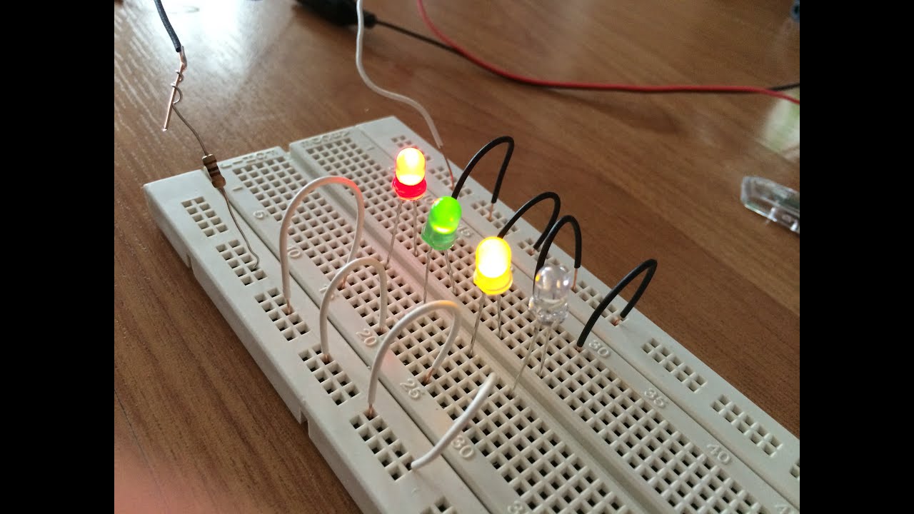
Add 7 more leds to the right of the first one.
Let us discuss how to use breadboard for beginners, consider designing simple led circuit which makes the led to glow using a power supply through a resistor for controlling the power to led. Lastly, turn on the battery to illuminate the led. Connect one end of a jump wire to the anode of an led and the other end of the jump wire to the positive terminal of the battery. Then connect the resistor from the same row on the breadboard to a column on the breadboard, as shown above.
In the example, pins 13, 12, and 8 are being used.
Connect its one pin to a0 (analog pin) of arduino, and connect its pin to gnd pin of arduino. Insert the led into the breadboard. Connect its one pin to a0 (analog pin) of arduino, and connect its pin to gnd pin of arduino. Attach wires to any of the holes in the same row to make an electrical connection.
Wire connections to 5v are typically red, and those connected to ground are black.
Start by bending the longer lead of the led as shown in the previous photo. Next, push the leds legs into the breadboard, with the long leg (with the kink) on the right. Insert the longer led lead (positive side, or anode) into hole 9j (that is, the hole located in row 9, column j ). We can add or skip the resistor because the battery already provides a limiting current.
Afterward, click the red wire to the battery’s negative terminal and the breadboard’s top rail.
The bus strips are separated at the 30th row in this breadboard. Make sure they're all in column b, and don't leave any spaces between them. // turn the led on (high is the voltage level) 11 delay (1000); // turn the led off.
Just like before, we want to connect the led and resistor in series to pin 13 and ground.
Connect the cathode of led to gnd of arduino. Simple led with 555 ic. All you need is a breadboard, a 9v battery, 100 ohm resistor and l.e.d ( light emitting diode ) Connect the external power supply through binding posts or.
Connect a wire from the resistor to pin 13 on arduino (digital pin).
This is shown here with the orange wire. Testing for almost every electronic projects starts from the breadboard. The connection setup is listed in the below steps: Add a black wire connecting pin 1j to the negative power rail on the top of the breadboard.
// wait for a second 12 digitalwrite (11, low);
Insert the led into the breadboard. Lastly, complete the circuit by connecting pin 18 to the right hand leg of the led. Standard wires cannot be used for breadboard as they get damaged easily 1 // the setup function runs once when you press reset 2 // or power the board 3 void setup { 4 // initialize digital pin 11 as an output.
If you have a protoshield, make sure its assembled first.
Connect a jumper wire from pin 13 on the arduino to the same row containing the top leg of the led. Connect a jumper wire from the positive leg of each led to the arduino pins. Plug your leds into any two rows on the breadboard with the long leg (positive) toward the top of the breadboard. Place the led sensor in the breadboard;
The leads that most elements have can easily be pushed inside these holes.
We're going to now use the breadboard to light up an led. Plug the longer lead (anode) of the led into the top rail of the breadboard and the other lead into a hole in the main part of the breadboard as shown: