This will power the breakout board and led directly from the supply connected to the dc power jack. Connect arduino ground pin to transistor emitter pin. Download scientific diagram | 19:
Arduino and RGB led examples Get electronics
For gnd, receive and transmit.
Start from open arduino ide.
// the number of the led pin // variables will change: The leds are individually addressed and codes have to be transmitted to them. In case you have the led, the resistor and breadboard you can connect all together following the schematic below. Arduino code /* blink turns on an led on for one second, then off for one second, repeatedly.
*/ // the setup function runs once when you press reset or power the board void setup() { // initialize digital pin 13 as an output.
Put your arduino nano on the breadboard. // initialize the pushbutton pin as an input:. Copy the above code and open with arduino ide. Ir led connection with arduino [11] from publication:
Connect to the arduino as follows:
The first thing you can do is to connect the power to the 5v pin of the uno board. Connect that leg to a gnd pin of the arduino, using a black cable if possible (convention for gnd). To connect an led to the arduino, you need to understand where on this board will be the plus, where the minus. Connect arduino to pc via usb cable.
Here we show v+ connected to the arduino vin pin.
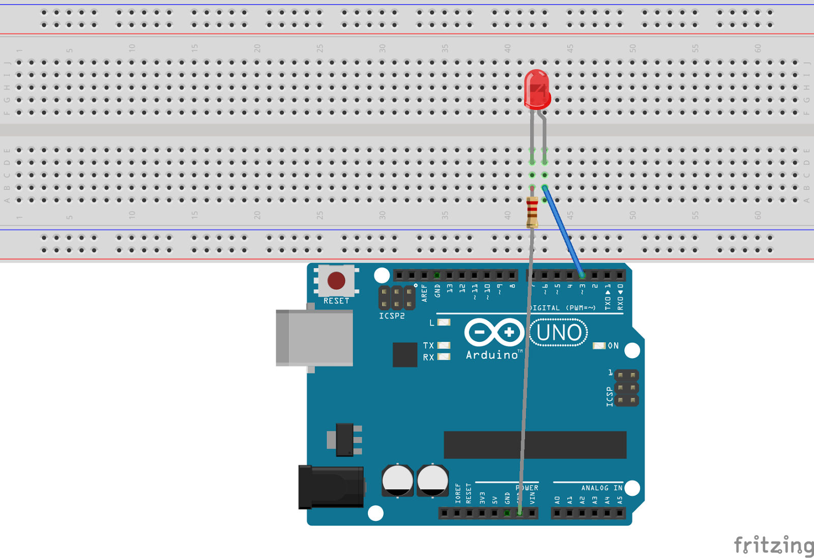
For its work, you need an electrical circuit with a plus and minus. Connect the positive leg of led which is the longer leg to the digital pin 6 of arduino. Controlling brightness of led through code (pwm control) firstly, make the connections as shown below. The arduino can only supply about 40 ma per pin max.
Both of these wires go into a mini “rayexelec” breadboard.
Automatic level crossing system | this report presents. So you can just add a black wire here and a red wire here. With the ws2812b addressable led strip, you can control the. // variable for reading the switch status int brightness = 0;
The amazing but not important code arduino.
Plug the longer leg of the led to a different hole, on a different and independent line of the breadboard. The longer wires on the leds are positive and the shorter wires are negative. First, connect the four leds to the arduino. Plug the shorter leg of the led to a hole on the breadboard.
// sets the led off delay (500);
Const int buttonpin = 2; Then connect the 220 ohm resistor to the negative leg of led and connect the other end of resistor to the ground pin of arduino. Resistor (220 ohm) one leg attach to led long leg. The green wire attach to resistor's empty leg.
Dc 5v ws2812b 5 meter, 60 addressable led strip is the coolest type of led strips.
// waits for a second } Here we are using “d7” pin from arduino mega. This led is connected to a digital pin and its number may vary from board type to board type. Connect power supply (12v) positives pin is connected to led positive terminal and negative pin is connected to transistor emitter pin.
Then connect the ir sensor to the arduino.
Conecta la resistencia entre el pin digital 2 de arduino y el positivo del led. Connect arduino digital 13 pin to 2.2k resistor and connect the resistor to transistor base pin. Okay, now that we have this down, im gon na search for rgb led and just take it here and plug it. Your leds will require about 1000 ma or so per channel (based on the 3 a psu supplied with the unit).
// sets the led on delay (500);
Void setup() { // initialize the led pin as an output: The resistor is wired to digital pin #3. Conecta el pin gnd al negativo del led ) First, you connect the ground here of the bright board to the ground of the arduino and 5 volt of the breadboard to 5 volt of the arduino.
Press and keep pressing the.
Click upload button on arduino ide to upload code to arduino. } void loop () { digitalwrite(led, high); The tact switch is wired to gnd and two digital pin #2. // the number of the switch pin const int ledpin = 9;
// turn the led on delay ( 1000 );
Connect the positives of the four leds to the pins 7, 6, 5, and 4. So actually lets play it here. Connect the negative of the four leds to gnd on the arduino through the 220 ohm resistors. To make your life easier, we have a constant that is specified in every board descriptor file.
// waits for a second digitalwrite (ledpin, low );
Copy and paste this code into your arduino ide or web editor #define led 13 // the pin the led is connected to void setup () { pinmode ( led , output ); Lets look at that code again void loop () // run over and over again { digitalwrite (ledpin, high ); Wire the gnd pin to the negative of the led (coloca el arduino nano en la protoboard. // declare the led as an output } void loop () { digitalwrite ( led , high );
Void setup () { pinmode(led, output);
After all, an led is an electrical device. If you look up the specs for your led, you will notice the forward voltage (vf) and the amount of current (imax) for the led. Open the new sketch file by clicking new. // turn the led off delay ( 1000 );
A tact switch, an led and a 1k resistor is added to a breaboard.
The usb is connect from my computer into the uno (for dev purpose). Use that information to calculate how much series resistance you will need. A more typical value for an led is around 2v and the current can be lower so a common value is a. The led is wired to gnd and the 1k resistor.
There is a cable connected directly into the eithernet board, and this works (confirmed by twitter example i am receiving the led on) there are two wires coming out of the arduino (gnd and pin 8).
// wait for 1000 milliseconds (1 second) digitalwrite ( led , low ); Wire the resistor between the arduino digital pin 2 and the positive of the led. Coding in the arduino language will control your circuit. Both arduino setups have the basically the same wiring: