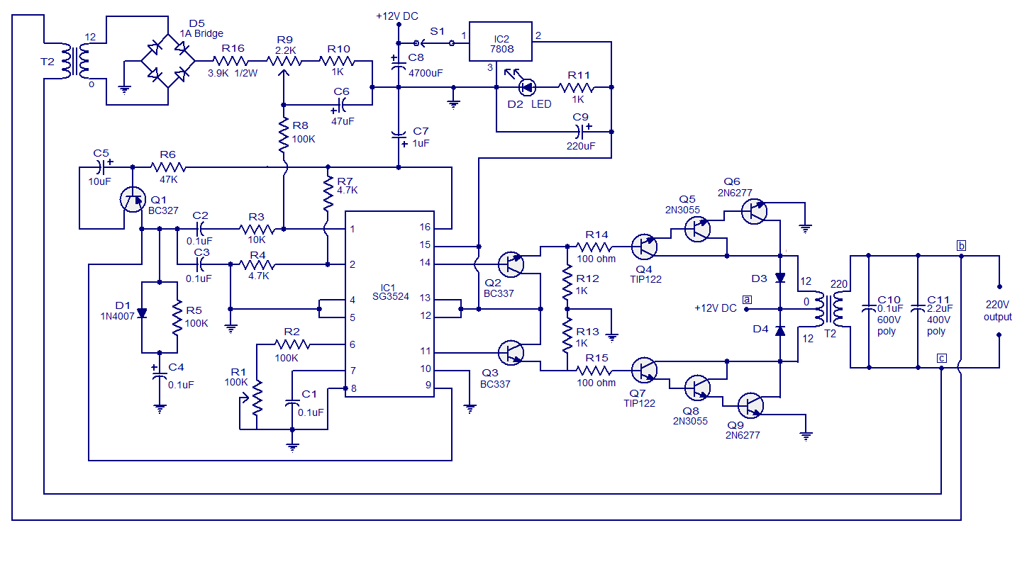
Center tap transformer is used in this project. Step up transformer is used to step up voltage from 12 volt to 220 volt ac. Parts list for the 220v inverter circuit using sg3525 and output voltage correction feature 3) inverter circuit using ic sg3524 this 3rd design is easy to build, the output power of 150w, the present simple inverter circuit using ic sg 3524 design frequency of about 300hz, the purpose is to reduce the volume of the inverter transformer, the weight, the output waveform is.
SG3524 PWM INVERTER CIRCUIT Many circuits
This is an sg3525 based inverter schematic.
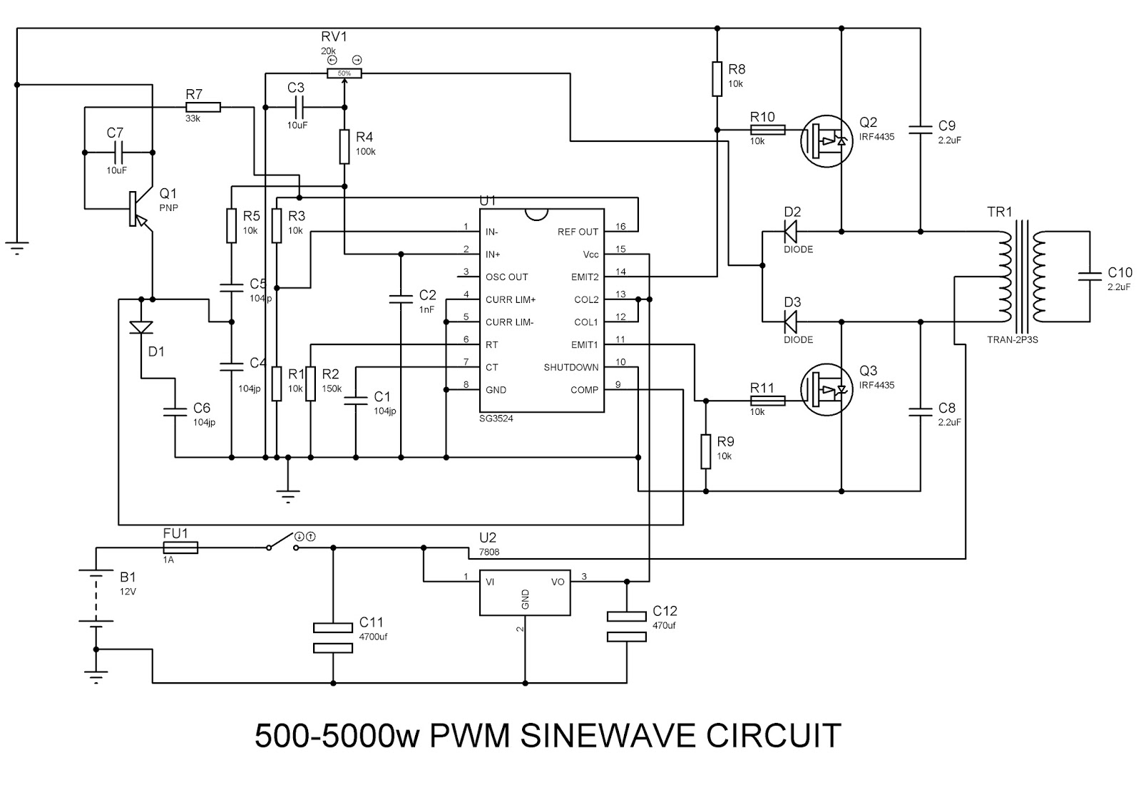
Inverter circuit using sg3524 07/05/2009 4:41 pm here is a 500watt inverter circuit.
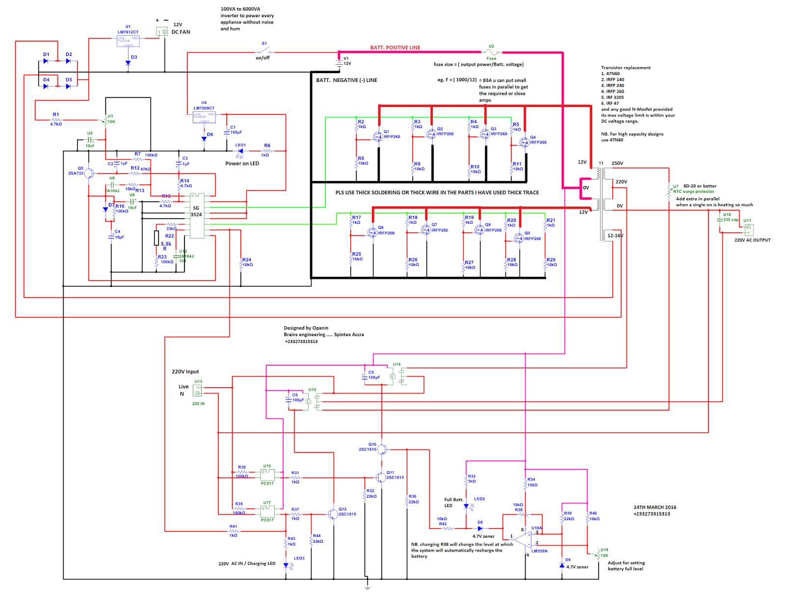
This inverter circuit contains three stages, pwm switching pulse generator; Voltage divider circuit at the output is used to give feedback to sg3525. Pin 10 of sg3524 is shutdown pin. Stay safe while building this.
And transformer giving little noise.
The output can be smoothly adjusted from. Users can adjust the width of pwm. Second inverter using sg3524 is almost ready. Hi, in today's video i'll show you how to make a regulated power inverter with the popular sg3525 or uc3525 pwm ic.
The sg3524 ic integrated circuit has all the functions necessary for the production of a regulating power.
The sg2524 and sg3524 were designed for switching regulators of either polarity, transformer. This involved electric current high enough to kill a person. Circuit diagram of solar inverter using sg3523. Circuit diagrams of example below show the circuit diagram of sg3525 which generates two inverted pwm signals.
Sg3524 is powered on with 8 volts using 7808 and 547/557 are powered on using 7812.
And we will build the 12v to 230v inverter circuit using pwm ic sg3525. Feedback control in sg2524/sg3524/sg3525 inverters. Inverter circuits are too many. Can you please guide me from here.
Hey guys, i've been searching for the circuit of an inverter using sg3524 for about a month.
Circuit diagrams of example below show the circuit diagram of sg3525 which generates two inverted pwm signals. You can change the variable resistor value to adjust the resolution of pwm. Here is a simple pwm dc to ac voltage inverter circuit based on ic sg 3524. Logical 1 on pin 10 will shutdown the inverter and protect your output.
How to make inverter ( 100 watt 200 watt 300 watt 500 watt ) using sg3524 ic & p55nf06 , irfz44n or irf3205 mosfetin this video tutorial i have attached an i.
I just want a circuit of an inverter that is. Here we are mainly using the internal oscillator of pwm sg3525. One of the mosfet is heating up without any load in 5 to 20 seconds. They are also called power inverters.
The first example circuit belw shows how an automatic feedback control can be added to a sg2524 inverter circuit.
The same concept can be also applied to all the other inverter versions, using. Inverter circuit diagram using sg3525 and mosfet a 250w pwm inverter circuit built around ic sg3524 is shown here. You need to sense your load either from the sources of your fets or from the output of the inverter. While the second one is cool.
Simple and powerful pwm inverter circuit diagram designed with ic sg3524 (regulating pulse width modulator) gives upto 230v ac from 12v dc supply.
In this circuit diagram push pull topology of dc to dc converters is used to converter dc voltage source into ac voltage. But i am having an issue. Now i think it’s time to introduce an inverted that has one of the best inverter efficiency. This is very very efficient as compared to the one you provided.
Users can adjust the width of pwm using a variable resistor shown in the feedback circuit.
Please swag for modified inverter using this sg3524 circuit without conversion to pure sine will sziklair pair work better than ordinary transistor at the output pin 11 and pin 14.