To protect against damage that may occur. This circuit is envisaged frequency in 300hz. I found out that the inverter was over loaded.
Proposed 5level inverter circuit Download Scientific
Overload protection circuit, output drivers etc.
The inverter overloads in the following scenario:
At the same time a monitoring current inverter is turned on to deliver current to the load at a very low power level. Sg3524 forms the heart of this pwm inverter circuit which can correct its output voltage against the variations in the output load. We see the protection circuit. Abstract—in this paper, an overload and short circuit.
An overload protection system for a power inverter utilizes a first circuit for monitoring current to the load from the power inverter to detect an overload and a control circuit to shut off the power inverter when an overload condition is detected.
Thus the opamp will trigger its output in high state if current_sense is greater than 5.7v and will trigger its output low when current_sense is smaller than 4.5v. This is a kind of excellent performance power inverter for home circuit diagram, materials are easy to get, and the output power can reach 150w. Which is divided into 3 sections: Free pcb layout ( suitable for using ic sg3525, sg3524, etc.
Ac mains low/high voltage protection.
In order to achieve high reliability and availability of the ups, short circuit and overload protection scheme are necessary. Inverter protection circuit diagram inverter. The frequency generator stops the output transistors. The protection will stop the operation of ic2.
The following diagram shows a simple battery overload controller circuit using a single opamp 741 and a relay driver stage.
Sg3524 pwm inverter circuit diagram. If there is malfunction occurs. It is a very important and useful circuit board for inverter voltage detection and shutdown to protect electrical equipment. This is based on the mosfet3205.
Usually a low value resistor is normally used at the output of mosfet amplifiers, the current designed across this resistor could be well used for tripping a relay just in case it.
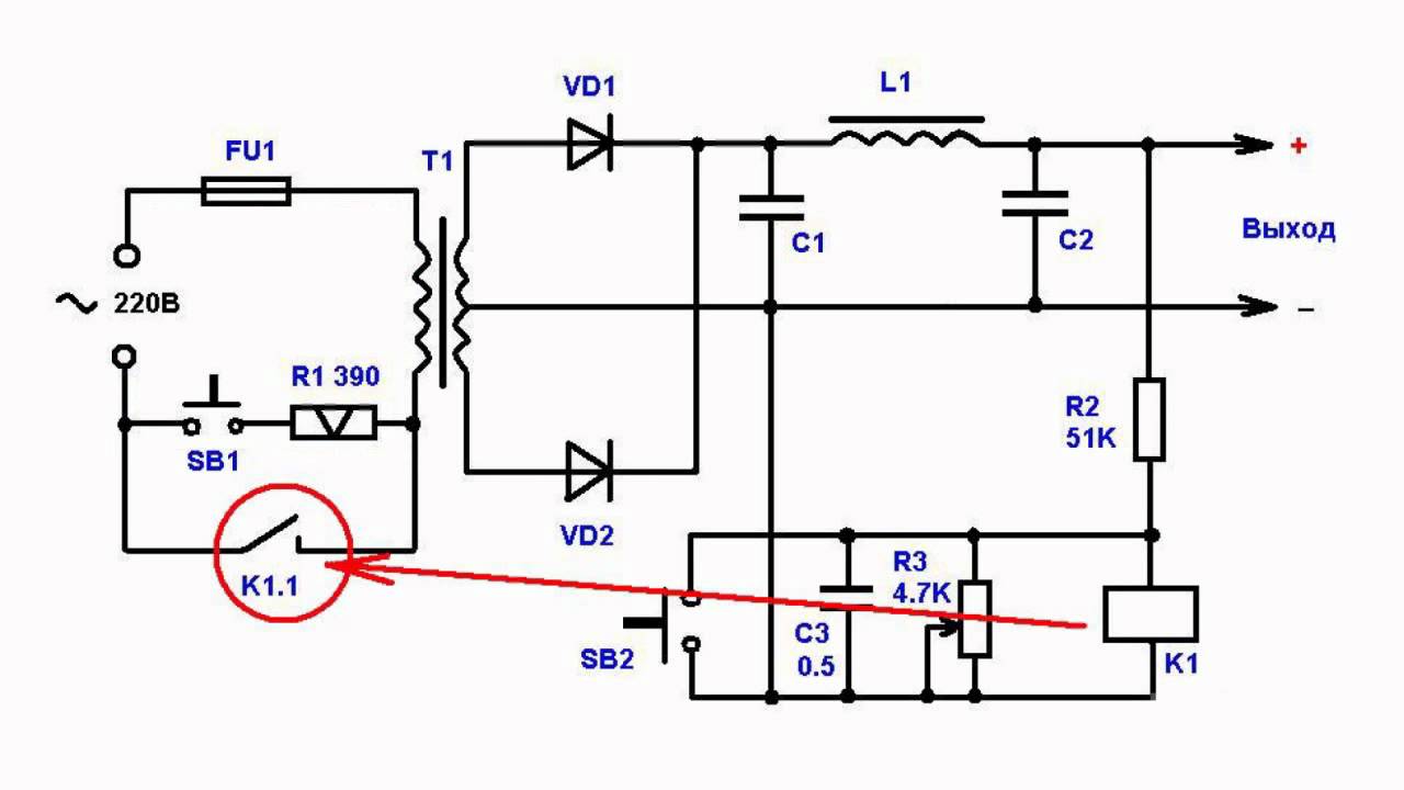
Figure 1 the overload protection for transformer. So i thought of installing an overload protection. When the overload occurs, scr1 is triggered to work or conduct. Battery charging in four steps.
Diode sensing is made by an internal circuit that compares the
Recently i burnt all the four mosfet. He inverting input of the opamp is clamped at. Ton=ln(2)*(ra+rb)*c (2) toff=ln(2)*rb*c (3) since the factor ln(2) is the same for both the ton and toff, and (ra+rb)> rb, so ton>toff, and the duty cycle> 50% figure 2 shows the outer circuit connection for the traditional astable 555 timer. Protection circuits of the inverter:
Thus, no overload situation is encountered;
When the current flowing through the inverter device reaches an abnormal value (exceeding the allowable value) due to a short circuit on the load side of the inverter, etc., the inverter will be stopped instantaneously to cut off the current. The r2 reduces the current of led1. If the battery voltage is low the buzzer starts to beep. First appliance 300w + second appliance 900w = 1200w.
You have to adjust r1, r2 to get the desired thresholds voltage difference.
Simple and practical 150w power inverter circuit. If we switch on the first appliance, the load is 900w which is less than the rated capacity of the inverter. Click on image for best resolution click to. Use 24v dc supply for operation and connect 24v 5a or more than 5a transformer.
Protection method is proposed for voltage source inverter.
When overload or short circuit happens, using the proposed control method, the. A simple circuit shown below may be incorporated with a stabilizer circuit or any such protection circuit for reinforcing the safeguarding capabilities of the units. The opamp is configured as a simple comparator circuit. The vr1 controls the current of the load, and to set the limited current of scr1.
2000w inverter circuit diagram this is the circuit diagram of 2000w high power inverter circuit.
The purpose is to reduce the inverter transformer size and weight, output is square wave. The presented amplifier short/overload protection circuit diagram, demonstrates a cheap design utilizing just a single transistor for applying the meant feature. My circuity had auto charging with over voltage cutoff for battery. Please careful with this circuit because high a voltage.
How it works the diagram shows a very simple and straightforward configuration where only a couple of transistors and few other passive parts are used for forming the intending design.
The relay is running and contacts of the relay are in no position. Luminous digital inverter circuit diagram 750va. Specification of this popular inverter. (a) overcurrent protection circuit, (b) overvoltage protection circuit, and (c) under voltage protection circuit.
Inverter overload circuit diagram, egs002 sine wave inverter circuit many circuits, overload protection circuit in inverter edaboard com, design and construction of 1kva inverter ijeert, power inverter wikipedia, inverter help overload protection bypass, contactors and control circuits claydons org, electronics circuit diagram and electronics.
If you switch the second appliance, the total wattage needed is as follows: