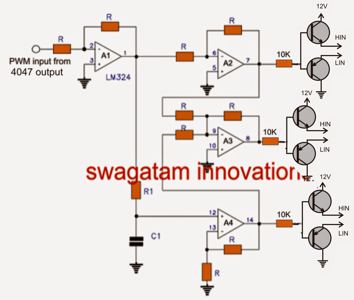
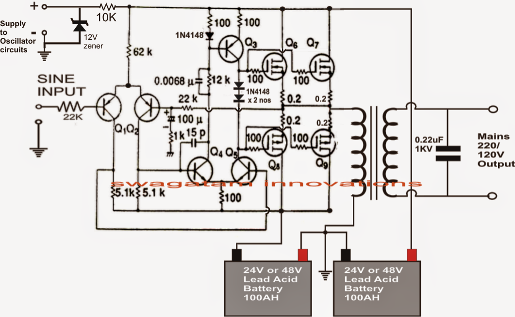
The circuit will alternately store energy in the capacitors (electrical energy) and in. Thus, the signal will run from ica to ic1c and backward to ic1a in cycle form. The oscillator will produce digital square wave.
An oscillator of the 200 watts power inverter
The problem if you don't use a schmidt trigger inverter or gate, is that they can (and do!) tend to latch up with a slowly changing input voltage.
The only 2 components that we have to add externally to the 7414 chip is a resistor and a capacitor in parallel.
An electronic oscillator is an electronic circuit that produces a periodic, oscillating electronic signal, often a sine wave or a square wave. Take your first oscillator, and add two more inverters. Let us assume that node a in the circuit is 0. Then, use an oscilloscope to measure the waveform signal at the output of ic1d.
Ic crystal oscillator circuits the majority of ic’s with built in crystal oscillator circuits use the gated pierce design where the oscillator is built around a single cmos inverting gate.
You can make a simple oscillator with an inductor (a coil) and a capacitor (two parallel plates). Lc inverter oscillator introduction an oscillator is an electronic circuit that produces a periodic signal. This exercise will examine a oscillator that produces a ttl type signal using a digital inverter The circuit we use a little equipment, just add a resistor and capacitor are the only one, it uses less energy.
This circuit is called a phase shift oscillator.
Java@falstad.com generated wed dec 7 2016 Inverters already have the necessary 180' phase shift and only need a single r and c to make an oscillator. The circuit shown below is a schmitt trigger rc oscillator using a digital schmitt trigger inverter gate. See in the circuit, we connect the inverter ica to icd continuously series.
Oscillators convert direct current (dc) from a power supply to an alternating current (ac) signal.
The second inverter will drive node b to 1. Generally they are less likely to latch up if you use a lower value resistor (more rc current). Then the third inverter will drive node c to 0, the fourth inverter will drive node d to 1 and the fifth inverter will drive node e to 0. This will result in an output frequency of approximately 70 mhz (which i simulated in circuitlab).
Introduction this report focuses on dc to ac power inverters, which aim to efficiently transform a dc power source to a high voltage ac source, similar to power that would be available at an electrical wall outlet.
This example shows how two cmos inverters can serve as an oscillator, using feedback. The phase shift provided by the inverter is 180 degrees. But the led oscillator circuit. The output of ic1c will feedback to the input of ic1a.
In electronics, an oscillator is a circuit that generates a signal at a certain frequency.
They are widely used in many electronic devices. Experiment square wave oscillator circuit using inverter pattern. In an oscillator circuit, the cmos inverter operates in the linear mode and works as an amplifier. An oscillator stage is perhaps the simplest part in an inverter circuit.
The oscillator circuit utilizes a pierce oscillator design with three inverter stages connected in series.
They are fundamental elements in telecommunications, electronic test instrumentation, sequential digital systems, and numerous other applications. R1 connects the circuit in a positive feedback loop necessary for oscillation. When we switch this circuit on (meaning when we hook it up to a source of energy, such as a battery), at the output we will obtain a sine wave, whose amplitude and wavelength will depend on which amplifier, resistors,. An oscillator circuit is the crucial circuit stage in any inverter, as this stage becomes responsible for switching the dc into the primary winding of the transformer.
This in turn will make the first inverter drive node a to 1, which is
To meet the oscillating condition, the


