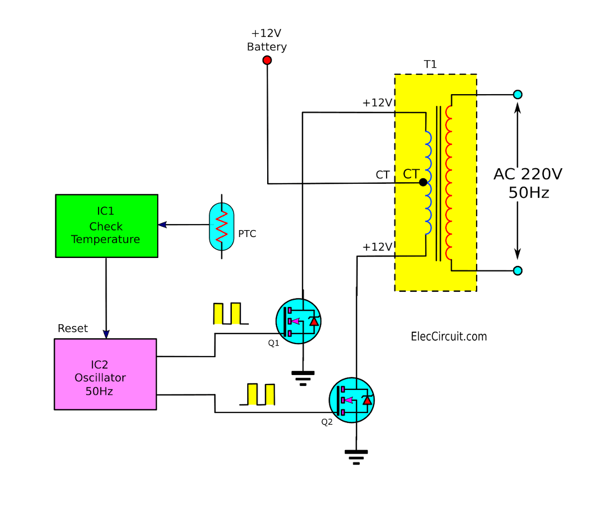
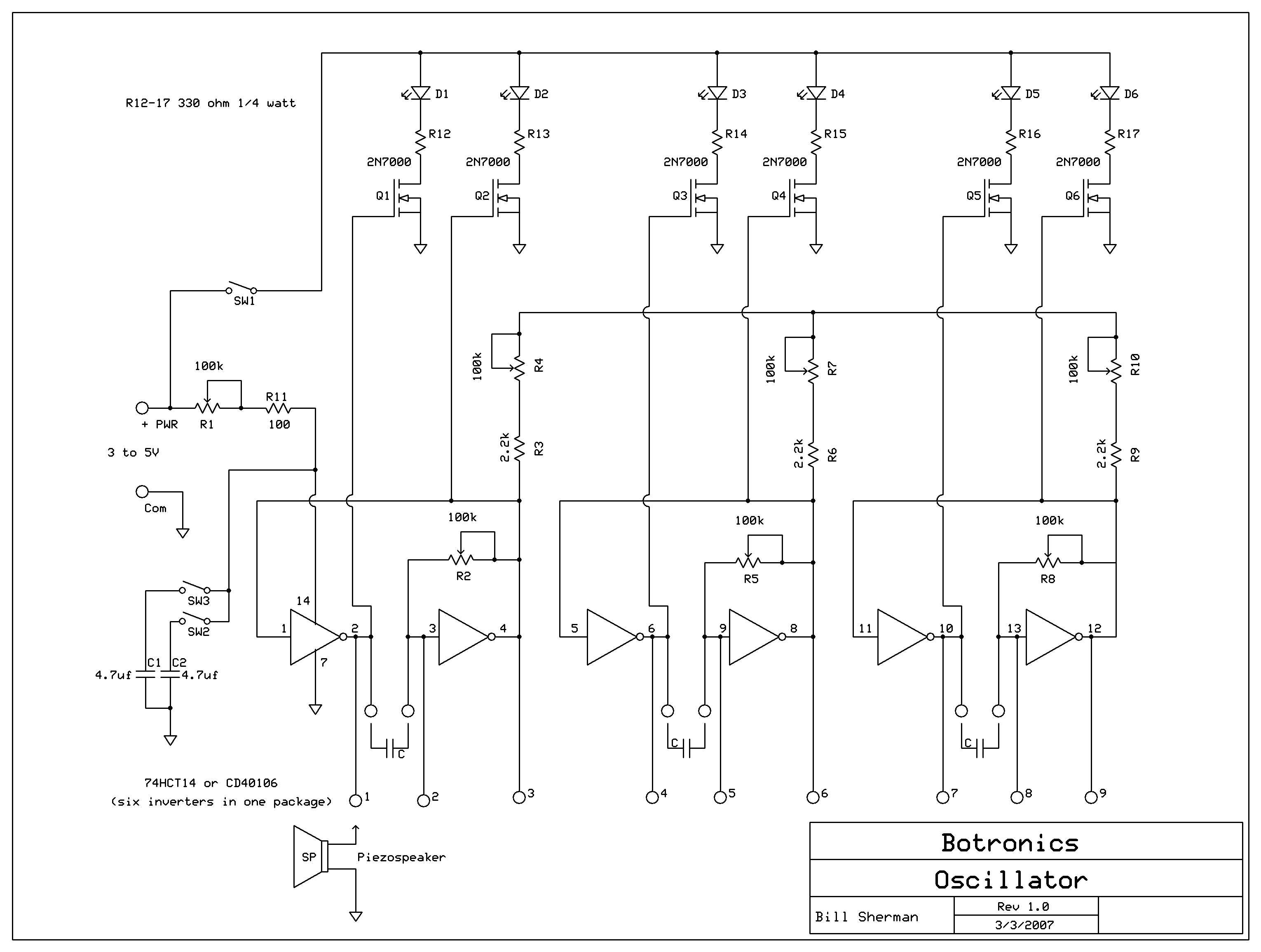
Then, use an oscilloscope to measure the waveform signal at the output. Simple digital signal inverter project schematic circuit diagram. The below figure shows the ring oscillator layout.
How to Design an Inverter Basic Circuit Tutorial
This circuit has operating frequency range of 10khz to 10mhz.
C1 = 0.01uf, c3 = 0.1uf;
A 250w pwm inverter circuit built around ic sg3524 is shown here. 9/06/2015 · 230v, 50hz, 1.5kva, full bridge pure sine wave inverter circuit using sinusoidal pulse width modulation. R2, r3, r4, r5 = 1k, t1, t2 = irf540; Home decorating style 2022 for sine wave inverter oscillator circuit diagram, you can see sine wave inverter oscillator circuit diagram and more pictures for home interior designing 2022 324155 at resume example ideas.
250w pwm inverter circuit sg3524.
For proper operation, pin 1 and 5 should be connected together. This can be made from igbts, power mosfets or gtos, depending on power. D1 is blocking and c2 is out of circuit, so the oscillator frequency is high. R1 = 220k pot, needs to be set for acquiring the desired frequency output.
A pure sine wave, after passing it through an lc filter.
Parts list for the above explained 150 watt inverter circuit diagram: This effectively adds c2 in parallel with. The frequency is not determined only by the crystal, but fine tuned further by c and r that determines the exact operating frequency of this circuit. Home decorating style 2022 for pure sine wave inverter oscillator circuit diagram, you can see pure sine wave inverter oscillator circuit diagram and more pictures for home interior designing 2022 324105 at resume example ideas.
600va inverter circuit diagram 12v va inverter project using a transformer salvaged from ups.
Three phase inverters require microcontroller design where the timings of the all three phases need to be precisely timed and executed. Automatic ups system wiring circuit diagram for home or office new design with one live wire wiring and installation. Java@falstad.com generated wed dec 7 2016 The 2n3055 piece and 5watts 220 or 330 register 2 pieces.
The built in circuitries inside the sg3524 include pulse width modulator, oscillator.
Thus, the signal will run from ica to ic1c and backward to ic1a in cycle form. However, when q1 is turned on (in saturation), it carries charging current for c1 and the diode d1 provides a discharge path. An oscillator stage is perhaps the simplest part in an inverter circuit. Simple 12v fixed voltage power supply circuit diagram;
An oscillator circuit is the crucial circuit stage in any inverter, as this stage becomes responsible for switching the dc into the primary winding of the transformer.
One is a more common inverter circuit diagram. See in the circuit, we connect the inverter ica to icd continuously series. With this contact, the input. In the following diagrams we see a few popular oscillator circuit designs, the outputs are square wave which are actually positive pulses, the high square blocks indicate positive potentials, the height of the square blocks indicate the voltage level, which is normally equal to the applied supply voltage to the ic, and the width of the square blocks indicate the.
In this inverter i have opted to use a sg as the main oscillator.
Introduction this report focuses on dc to ac power inverters, which aim to efficiently transform a dc power source to a high voltage ac source, similar to power that would be available at an electrical wall outlet. This ic is specially made for use with pulse width power supplies. Here is the schematic diagram of the. This example shows how two cmos inverters can serve as an oscillator, using feedback.
This is a 71 stage oscillator to produce the signal at 27mhz frequencies.
The output of ic1c will feedback to the input of ic1a. The inverters which are used in this oscillator are connected using l1m1 and pyl1 contact. Wise tech november 24, 2020. Pin 14 is vdd and pin 7 is vss.
The internet is flooded with single phase inverter circuit diagrams, but there are only few circuit diagrams of 3 phase inverter out there, a simplest possible 3 phase inverter is described here.
Pulse width modulation is generally used to drive a high power class d switching amplifier. Experiment square wave oscillator circuit using inverter pattern. This circuit uses cd4007 or mc14007. R5, preset p2 and c1 set the oscillator output frequency.5/5(1).
That's why erniem's circuit (with a single inverter) shows three rc circuits with each one providing 60° of shift.
Inverter circuit 500w 12v to 220v eleccircuit com. Most of the inverters available in the market have complicated circuit design and are not very I have included circuit diagram using igbt, pic18f886 circuit diagram, assembly language program for pic16f886 and hex file in pdf format. Software controls the pwm duty cycle so that it smoothes out to being a.


