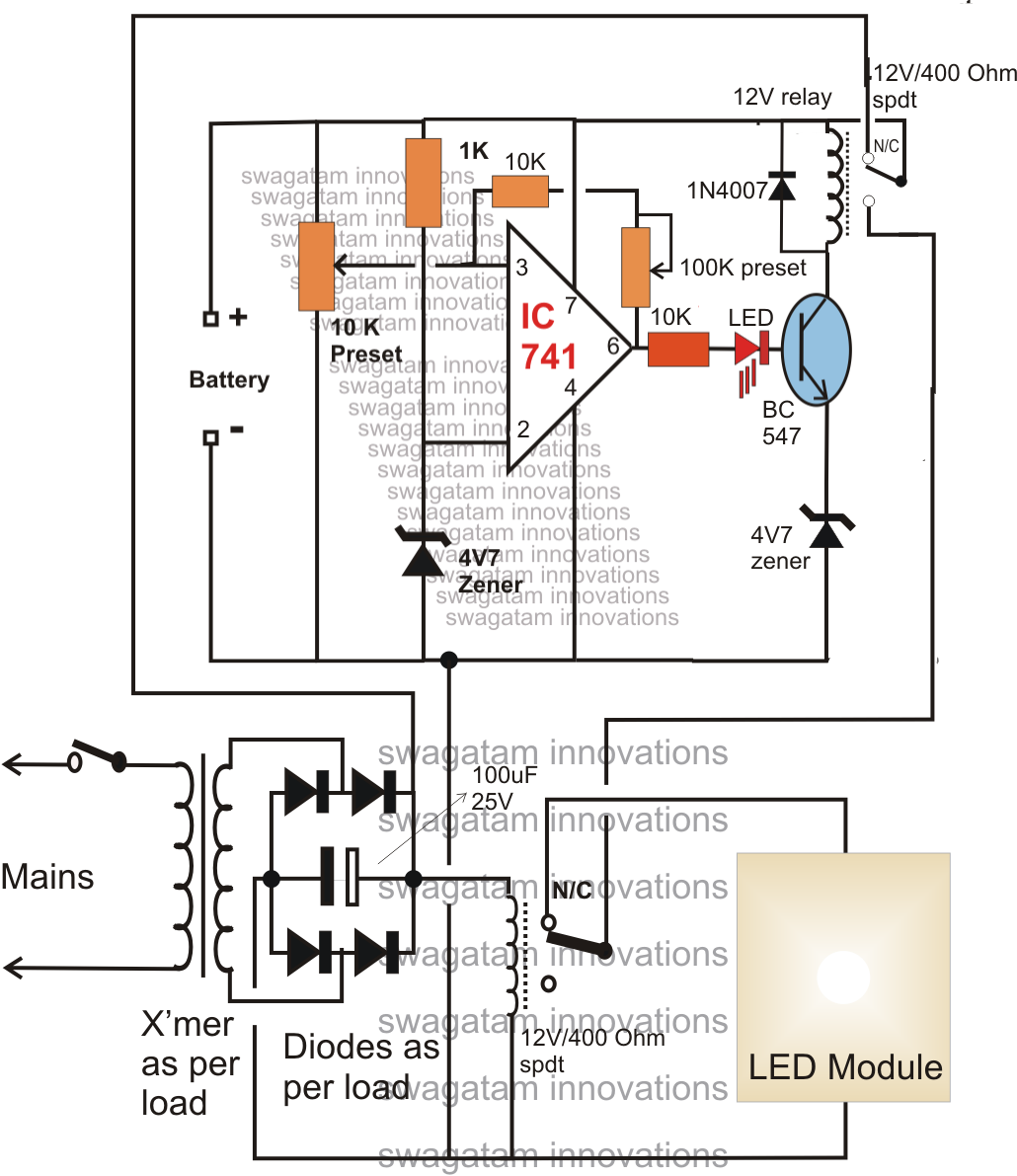
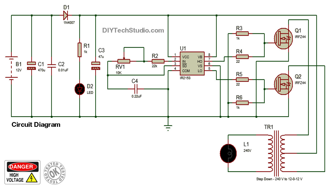
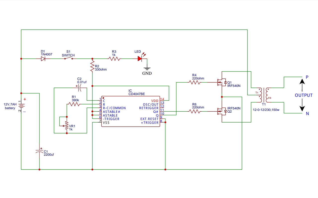
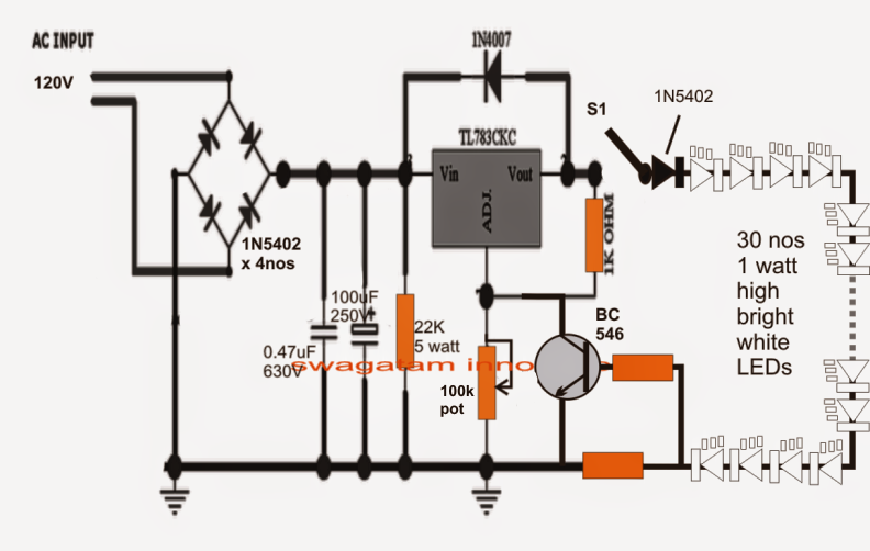
Led lamp circuit circuitdiagram org electronics circuit led lamp electronic circuit projects. Simple circuit diagram principialnaya shema kontur. Automatic led emergency light circuit simple bulb diagram 3 best circuits you can make at home homemade projects a 1 5v to 220v inverter step by diy electronics vm 12 14w rechargeable driver size 45mm dia ac rs 65 piece id 19521627712 80 vdc 98 9w acdc hpf ic warranty 2 year 32 22230172255 using mje13007 transistors lamp components explained.
20 Watt Tubelight Emergency Light Circuit Diagram
Meanwhile, we simply need to add a small circuitry mechanism to control the intensity of these led lights independently.
This inverter circuit uses two ic ne555 and sn74ls112 and 10 2n3055 transistor with some other components.
The voltage across the electrolytic capacitor is a little more than 52v. An inverter circuit can convert a dc signal of a nominal voltage strength (9v, 12v) to a substantially higher ac signal of the desired voltage level (220v). In the event of a power failure, an inverter is very useful as a backup power unit, and if optimally charged, will also allow you to use your pc, tv, lights, power tools, appliances, and. It is possible to adjust the frequency of the square wave by the pot.
Led are available in red, green, blue color.
Pin on 220v flasher bulb circuit. First, the main supply is given to the metal film capacitor. A simple inverter circuit diagram made by tl494 basic seekic com. Fluorescent lamp inverter converter schematic circuit diagram.
Use 24v dc supply for operation and connect 24v 5a or more than 5a transformer.
This is the complete circuit diagram and for pcb layout of this circuit click on the following link. The above circuit operates in the following manner: Mains operated led light circuit diagram. The second circuit uses chasing leds and is based on ic cd4017.
Circuitspedia.com electronic tutorials, circuit diagram, projects etc.
This is the circuit diagram of a 300w simple inverter. This is an easy inverter circuit based upon 13007 transistor. The capacitor 220n 400v behaves as a voltage dropping resistor and ensures that the current flowing is not more than 12 ma. This is the circuit diagram of high power 1250va digital inverter with charger.
This miniature inverter circuit can operate from 1.5v to 9v dc and can be used for powering small loads like 0.5 to 6 watt (120/220v) led lamps.
In this case, the leds just turn on one by one in a consecutive order. In the first circuit, we have implemented a flashing leds with the help of transistor based astable multivibrator. And they are increasingly using led lights with inverters to extend the amount of time that inverters can sustain led light. This inverter comprises of just 3 components and even a beginner can accomplish this project with ease.
We are using a 15w led bulb as our load but you can use any comparative ac load.
A switch allows the choice. We have created 4 different led running lights circuits using very simple components. Therefore, to control the splendor, we are utilizing the pwm (pulse width modulation) technique with a 555 timer ic. Circuit design of diy led light bulb.
A square wave is formed at the 3rd end of the 555 integral used in the circuit.
Fluorescent lamp is used in portable lighting devices with fluorescent lamps (searchlight) in inverter circuit. When we supply 12v to this simple. This inverter circuit uses two ic ne555 and sn74ls112 and 10 2n3055 transistor with some other components. This is based on the mosfet3205.
This is a safe value.
7 simple inverter circuits you can build at home homemade circuit projects. This inverter is sweet for little loads like 15w led bulbs, mobile charger, and other electrical accessories. 30 led projects led projects electronic circuit design. It can be a good project for school science fair or as an emergency light for your room.
Simple homemade inverter circuit diagram.
Now the simplified inverter stages are. The total voltage drop across the leds is therefore 15 leds times 3 v or about 45 v. The diodes 1n4007 bridge rectifier turns the ac voltage into a dc voltage i.e. Today, we are fabricating here an astounding rgb bulb utilizing red, green, and blue leds.
Typical wiring diagram emergency lighting mini central inverter system (black) (white) (blue) (white) (brown) (black) switched command signal (violet) earth ground (green) input wiring line switched output neutral normally on normally off output wiring neutral light fixtures (led, hid, incandescent or fluorescent) *cap off unused wires diagram #1
Image of the pcb layout of this high power inverter circuit diagram is given. Please careful with this circuit. The other end of the capacitor is connected to the ac input of a bridge rectifier. To understand how c1 functions, we can calculate the impedance (that is, resistance to ac voltage) as follows:
Light emitting diode are different from other diodes as they emit light and hence referred as light emitting diode.
Schematic of led bulbs for 230v 50hz line with 20ma leds led light bulb led lights led. This is the circuit diagram of a 300w simple inverter.


