But we have details that need to be learned. This software is used for diagram making. The spwm accuracy of eg8010 was not high enough waveform, so the inverter output was not good enough as pure sine wave.
Inverter Generator Wiring Diagram Free Wiring Diagram
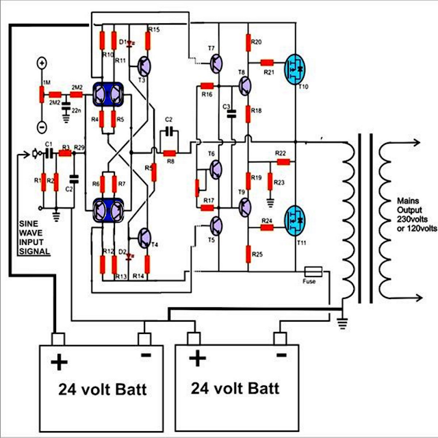
This is the circuit diagram of 2000w high power inverter circuit.
House wiring with inverter connection a s solution diagram diy charging car battery home circuit for 100 watt how an works working of to connect at your simple diagrams solar panel facebook china parrael easy made you can make in own sine wave full schematic typical 7 circuits build 200w db help.
Variety of inverter generator wiring diagram. The generator at the same time does not exceed that of the generator. Make this 1kva (1000 watts) pure sine wave inverter circuit. A suitable alternative is to use this 200w inverter circuit.
First, i recommend simple working principle of the inverter.
Please careful with this circuit. The circuit diagram for an inverter connection at home is given below. The square wave is fed to ic 4017 which will convert to modified sine wave at 50hz at 50% duty cycle. The common use of dc is in solar systems where generation occurs in dc so inverters are used to convert dc to ac.
The main circuit of solar on grid inverter is presented in the following diagram.
A s solution inverter wiring diagram diy charging car battery with home automatic connection solar power circuit of how an works working for m digital rv charger electrical wires cable easy made you can make 1000va grid tie installation 4 volts simple project circuits students design pdf. Power levels between rated and maximum may be used for no more than 30 minutes. Cd4047be 100w inverter circuit diagram with pcb layout soldering mind. Check that the startup surge will not be beyond the limit of the generator.
Modified sine wave inverter circuit diagram the circuit consists of ic 555 which is tuned to generate frequency at 200hz (square wave) at 50% duty cycle.
According to your requirement connect the. How to calculate the transformer rating. Mini power inverter schematic circuit diagram. The basic formula is p=vi and between input output of the transformer we have power input = power output.
A wiring diagram is a simplified traditional photographic depiction of an electrical circuit.
With this kind of an illustrative guidebook, you’ll have the ability to troubleshoot, prevent, and total your tasks without difficulty. The inverter is a device that used to transform the dc to ac in the electrical system. Few days ago, gohz made a 24v 2000w power inverter in home, sharing some design schematics and circuit diagrams. A relatively simple 1000 watt pure sine wave inverter circuit is explained here using a signal amplifier and a power transformer.
It reveals the elements of the circuit as streamlined shapes, and also the power as well as signal connections in between the gadgets.
Even robot systems occasionally need a negative supply voltage for some purpose or other, and in this kind of application, in particular, there is a need for an effective circuit that does not make greater demands then necessary in terms of current or space. According to the below circuit diagram you can see that during load shedding light 3, fan and t.v can be run by the inverter. Last updated on august 3, 2020 by swagatam 241 comments. You can use edrawmax for making a circuit diagram of an inverter.
Use 24v dc supply for operation and connect 24v 5a or more than 5a transformer.
Avoid substantially overloading which will trip the circuit breaker. Just like addany said, all u need to do is load separation, that's all, you remove the selected points/load that u want inverter to supply from ur breaker in ur db. This circuit is quite simple because we use ics and mosfets. Dc/ac pure sine wave inverter jim doucet dan eggleston jeremy shaw mqp terms abc 20062007 advisor:
If you have understood well.
Then at the input, we must have at least 18.3v at 12v because of 12v*18.3 = 220v*1. Schematic diagram of mig welding setup machine schematics service arc 200 circuit pdf smps inverter diagrams c3000i tig 3000i ac dc welder electronic. It contains all the necessary features and libraries that will. This is based on the mosfet3205.
The main use of dc in the solar system, batteries cells since these generate dc.
How to build 200w inverter circuit diagram project eleccircuit com. For example, if we want a 220w output at 220v then we need 1a at the output. 3:30pm on apr 03, 2016. Some models have the same control driver floors only igbt.
In the electronics or logic design subject, the inverter is also known as the not gate, which does nothing but logical negation.elaborating more, the inverter
As can be seen in the first diagram below, the configuration is a simple mosfet based designed for amplifying. The main function of an inverter is to convert dc to ac.