All the four devices may be n channel type or with two n channel and two p channel depending upon the external driver oscillator stage that's being used. Furthermore, you can utilize inverters to control the compressor motor speed to push the variable refrigerant flow during refrigeration. Its main function is to invert the input signal applied.
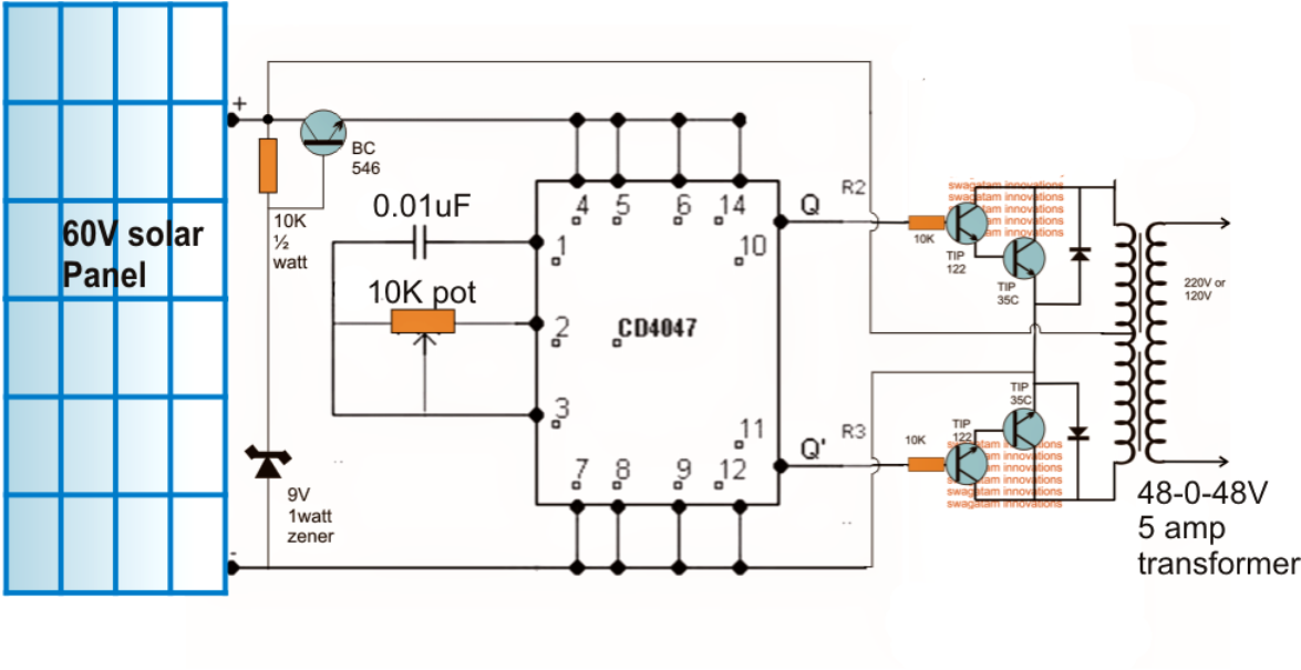
Low Power Square Wave Inverter Circuit using CD4047
This basic inverter circuit can handle up to 1000watts supply depends the t1, t2.
Sort by date sort by votes today at 2:28 pm #2 fvm super moderator.
The inverter is an electronic circuit that converts fixed dc supply to variable ac supply. Here i even have used 13007 transistors. A full bridge inverter circuit consists of four transistors or mosfets arranged in a configuration resembling the letter h. As a result, the circuit may require a large number of components to enhance the voltage.
Ic2, a 7812 regulator, controls the electricity.
Arduino enthusiasts must try this inverter as this is the simplest possible inverter which can be built using a microcontroller board like arduino. This current flows only in one direction. A power inverter circuit is a circuit that converts dc power to ac power. We can achieve 220v ac at the output of just 12 volts.
The following diagram is the basic design diagram of inverter circuit.
Inverters can be constructed using a single nmos transistor or a single pmos transistor coupled with a resistor. You can make the ac power be any level that you want and to any frequency that you want. In this circuit, the primary and secondary of transformer t1 is a 12.6 v to 220 v step down transformer, connected in the reverse format. There are several ways to create an inverter when an engineer needs to convert dc to ac electricity.
Inverters are also available as.
This is based on the mosfet3205. Its main function is to invert the input signal applied. Inverters allow the user to provide ac power in areas where only batteries can be made available, allowing portability and freeing the user of long power cords. 555 is a timer ic which is used to generate time delay.
On these properties, it can be used to make a power inverter.
Use 24v dc supply for operation and connect 24v 5a or more than 5a transformer. If the applied input is low then the output becomes high and vice versa. However, the term “inverter” generally refers to For instance, if we want to provide power supply to home appliances then it will use 230v ac.
Inverters do the opposite of converters which were originally large electromechanical devices converting ac to dc.
This is the circuit diagram of 2000w high power inverter circuit. An inverter is an electrical device, and it is capable of changing a dc current to an ac current at a given frequency as well as voltage. The alternating current is a current that consistently changes its magnitude with respect to time. In another vein, an ac inverter or ac inverter circuit adjusts the compressor speed to control the gas (refrigerant) flow rate, thus, consuming low power and current.
The resulting ac frequency obtained depends on the particular device employed.
The circuit will convert 12v dc to 120v ac. The input voltage, output voltage and. A power inverter, inverter or invertor is a power electronic device or circuitry that changes direct current to alternating current. The circuit in this article shows you a simple way to build a 12v to 230v inverter circuit diagram of 100watt power using 555 ic.
This simple inverter is constructed around an arduino board which gives very stable frequency of 50hz at 50% duty cycle.
One is a more common inverter circuit diagram. Joined jan 22, 2008 messages 49,747 helped 14,466 reputation 29,200 reaction score 13,342 trophy points 1,393 location bochum, germany The inverter is an electronic device used to convert direct current (dc) into alternating current (ac). On the market today are two different types of power inverters, modified sine wave and pure sine wave generators.
The output terminals of the inverter and the tweezers were scarred.
Please careful with this circuit. These transistors are connected like within the pic:1. 3 hours agopls i need short circuit protection circuit for my suoer 1000w china inverter. Simple inverter circuit using arduino.