So an inverter changes the logic state to the opposite logic of what is fed into it. When the input is high (+vs) the output is low (0v). By apichet garaipoom january 8, 2014 52 comments.
Simple inverter circuit using 6 transistor Inverter
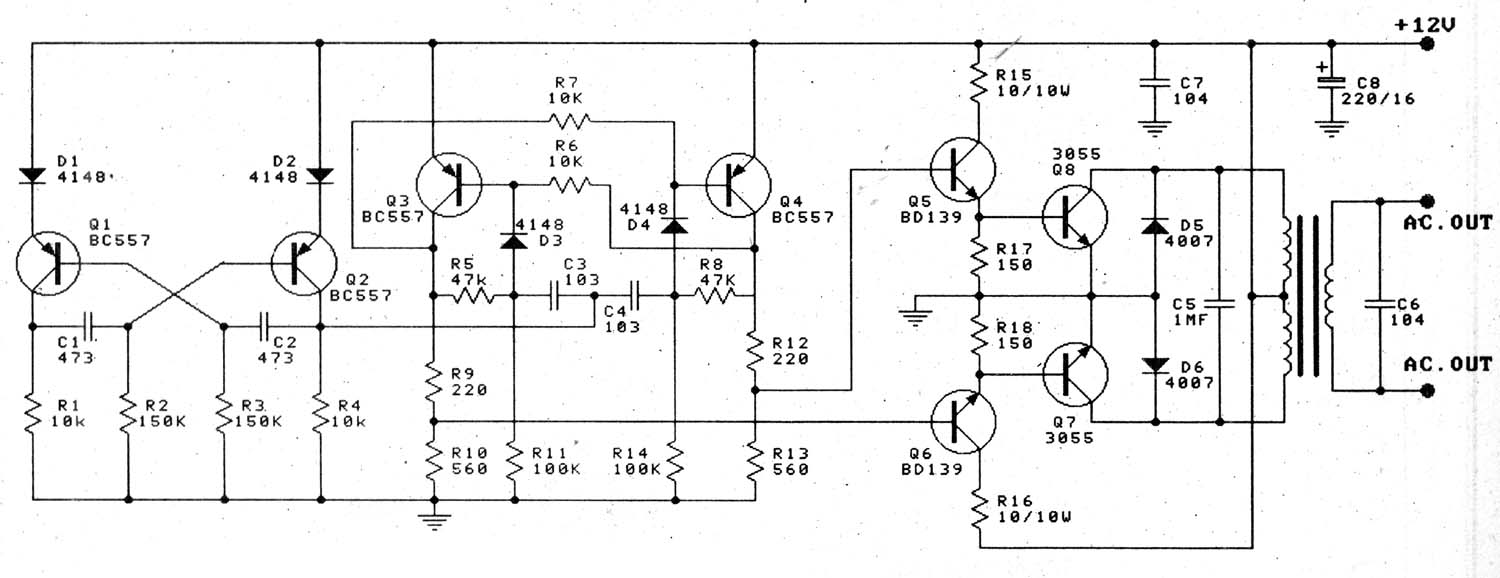
100 watt inverter circuit using 2n3055 transistors.
The transistors in the above circuit holds the most significant part in the working of this circuit where it was wired as a multivibrator.
In this circuit as you can see that the transistors q1 and q2 was wired as a astable multivibrator.as we know astable multivibrators has the capability to produce a constant square waveform.the astable multivibrator does not have any stable states.there will be two point of output from the astable multivibrator circuit. I'm not sure if i need to be using an output voltage function of time? In this circuit, we will build an inverter with a transistor. The transistor t1 remains conductive until the breakdown occurs.
In this transistor based inverter circuit, the oscillator design is built using a transistorized astable circuit.
Whether it’s in the car, boat, caravan or mobile home, this converter provides a mobile 220 v a.c. Its main function is to invert the input signal applied. This inverter consists of arduino board which the heart of this built, buffer stage with couple of bjt npn transistors, couple of mosfets as usual like on any inverter and lastly a buzzer. Ask question asked 2 years, 7 months ago.
To this end, the cmos inverter is in several electronic devices while offering data around small circuits.
Basically the resistors and capacitors associated with the bases of the transistors determine the frequency of the output. Referring to the circuit design below we can see that the inverter circuit uses just 4 transistors, a transformer, and a battery to implement a ful 100 watt power output from a small 12v 10 ah battery. In this video, we are going to show you making a inverter circuit. Transistors q1 and q2 forms a 50hz astable multivibrator.
In the transistor switch circuit, the.
On powering on the circuit using a 12v dc battery, a square wave signal is generated by the multivibrator circuit, but, in order to run an ac device without any issues, we require a pure ac sine wave signal form the. Thus, if a low signal is fed into an inverter, it flips it to a high isgnal. Simple inverter circuit using 6 transistors. This inverter is sweet for little loads like 15w led bulbs, mobile charger, and other electrical accessories.
When it is fully on it is said to be saturated.
An inverter is a component or device that inverts the state or logic level of a signal to the opposite logic level. Here is the circuit diagram of a fully transistorized inverter that can drive up to 60w loads. Here, we are using two 2sc1815 transistors, configured as a multivibrator circuit running in astable mode, in order to generate a free running square wave. Inverters can be constructed using a single nmos transistor or a single pmos transistor coupled with a resistor.
This is an easy inverter circuit based upon 13007 transistor.
Purpose:to reduce the size and the cost of an inverter by switching the power source voltage level of a base current supplying circuit in response to the magnitude of a load, and regulating the supplying base current of a main circuit transistor, thereby alleviating the switching loss. If the applied input is low then the output becomes high and vice versa. Using inverter you can operate your led light, c. The above circuit is known as digital inverter since obtained output wave was a square wave.
When we supply 12v to this simple inverter circuit one of the transistors goes into the conductive stage.
Viewed 778 times 0 \$\begingroup\$ i have been trying to understand this question and i'm just not sure what equation to use for the collector current. This part of the circuit provides the continuous square wave pulses needed for its working. The output from the collector of q2 is connected to the input of the darlington pair formed by q3 and q4.similarly the output of q1 is coupled to. Modified 2 years, 7 months ago.
Supply suitable for powering small electrical appliances, such as lights, soldering irons or.
Inverters (not gates) are available on logic ics but if you only require one inverter it may be better to use this simple transistor circuit. Constitution:a base current supplying circuit for driving a transistor inverter couples a. The output signal (voltage) is the inverse of the input signal: The major applications of inverter circuits include;
You can make this circuit at home easily.
If a high signal is fed into an inverter, it flips it to a low signal. When the switch is closed (or on), the led is off. Bipolar transistor inverter circuit analysis. A three phase inverter employs 6 transistor switches as shown above which are driven by pwm signals using gate driver circuits.
The circuit works with a push pull kind of operation where the q1 and q2 form a basic astable multivibartor for creating the basic 50 hz frequency.
Two types of control signals can be applied to run this circuit Working of inverter using transistors: The transistor inverter is implemented here using pn2222a npn transistor (a variant of the 2n2222a) but many common npn bipolar junction transistors could be substituted.


