So, in today’s tutorial, we will take a look into a step by step process on how you can build a simple 12v to 220v inverter circuit using two irfz44 mosfets. The main advantage of using mosfet as load device is that the silicon area occupied by the transistor is smaller than the area occupied by the resistive load. None of those schemes is good;
Pure Sine Wave Inverter Circuit Diagram Pdf Circuit
The designed system generates 223v square signals at each phase from a 12v battery through switching of three stages of power mosfets using pulse width modulation (pwm) signals at their gates from an arduino uno.
Inverter circuit is one of the fundamental building blocks in digital circuit design (not to be confused with a power inverter).
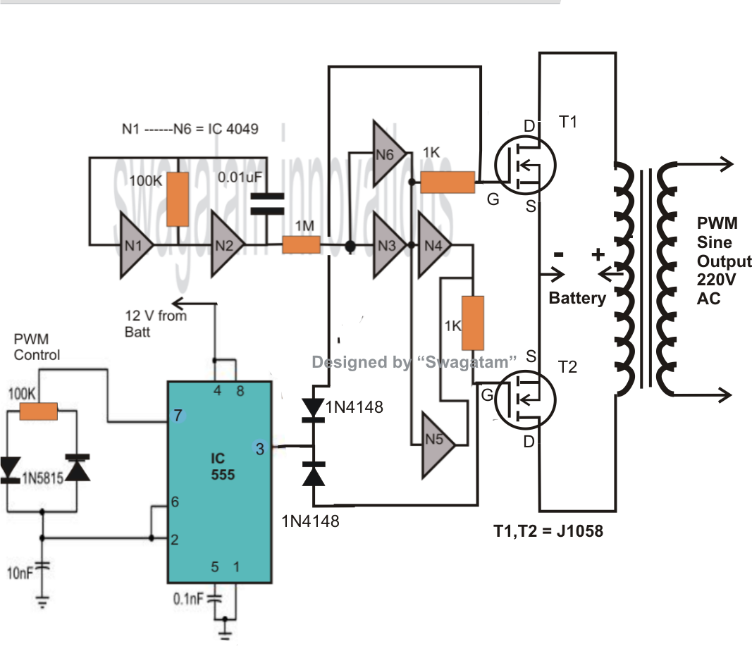
The lm324 is simply too slow to drive a mosfet gate in any inverter operating at a reasonable speed. N1, n2, n3, n4 not gates from the ic 4049 are arranged as a voltage doubler circuit, which generates about 20 volts from the available 12v supply. Upload the code to arduino first and start constructing the circuit. Using mosfet body diodes for charging inverter battery.
Here, mosfet is an active load and inverter with active load gives a better performance than the inverter with resistive load.
Mosfets are mostly used in cmos circuits. The word „inverter‟ in the context of power Goal • design logic gates using mosfets (nmos and pmos). This inverter circuit functions on the principle of converting a pure dc signal into a free running square waveform, through the help of a multivibrator circuit operating in astable mode.
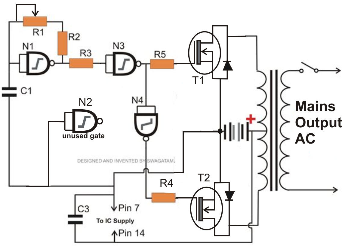
Ic based simple 12v to 240v inverter using mosfet & ic 4047:
Inverter, mosfet, relays, transformer, diode, ic. Turn the “switch 1” first let the arduino boot. The inverters can be applied directly to the design of logic gates and other more complex digital circuits. However, charging a battery requires a transformer, which needs to be a high wattage type to ensure optimal.
Inverter circuits can be very complex so the objective of this method is to present some of the inner workings of inverters without getting lost in some of the fine details.
A circuits and systems perspective,” 2011. There are many advantages of cmos, with the biggest being zero standby power consumption, at least ideally. According to properties listed in the table of figure 2. As 200 watts inverter circuit.
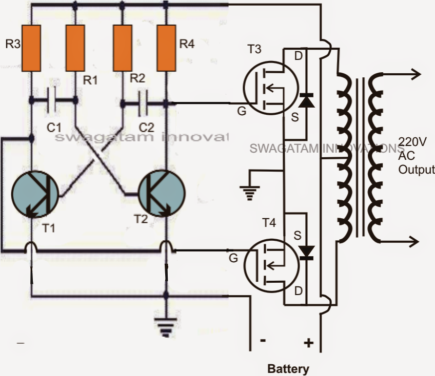
So this is just a basic inverter circuit built using a mosfet transistor.
• design 𝑆𝑆̅ using the inverted inputs and add an inverter at the output. In this tutorial we will show you how to make simple ic based inverter circuit. The output current at pin 3 of ic1 will flow two ways. We use q1, q2 is the mosfet acts as a power output.
The inverter circuit we will build with a transistor is shown below.
+ all static parameters of cmos inverters are superior to those of nmos inverters + cmos is the most widely used digital circuit technology in. If the circuit is fully functional with maximum power of 12v x 18a = 216 watts. They are used to drive bldc and other 3 phase motors. Inverter circuit diagram using sg3525 and mosfet a 250w pwm inverter circuit built around ic sg3524 is shown here.
F irst, through r3 to a gate of q2.
• complementary mos (cmos) inverter analysis makes use of both nmos and pmos transistors in the same logic gate. The mosfets are placed at x and y terminal and one of the two mosfets are turned on at an instant and in alternating manner. After completing the circuit, bring a fully charged 12v 7ah battery for testing. This project presents the design and simulation of 3 phase power inverter.
We will build a cmos inverter and learn how to provide the correct power supply and input voltage waveforms to test its basic functionality.
The transfer characteristics of an ideal inverter is shown below. Now you can turn on the “switch 2” which powers the mosfet and transformer. Whatever signal we feed into the input gets inverted to the opposite logic state at the output. You can watch the video which is embedded in this step for construction, parts list, circuit diagram & testing or.
Once the arduino booted you will hear a beep.
The breadboard schematic of the circuit above is shown below.