This software is used for diagram making. This is the circuit diagram of high power 500w inverter. Looking at the shown circuit diagram,.
500 Watt Inverter Circuit Diagram Using Mosfet Grow Amis
220v inverter circuit using irfz44 mosfet simple 100w with fet irf540 12v to 230vac rangkaian dc ke ac panduan 500w power circuits electrical4u 555 h bridge 4 n what is an diagram 7 you can high voltage easy 150 w full 100 watts working and for newcomers watt 500.
It is hard to find equipment.
Home decorating style 2022 for inverter circuit diagram using mosfet, you can see inverter circuit diagram using mosfet and more pictures for home interior designing 2022 317355 at resume example ideas. Simple 12v to 230vac inverter circuit. Simple low power inverter circuit | 12v dc to 230v or 110v ac | diagram using cd4047 and irfz44 power mosfet. How to make simple inverter circuit diagram within 5 minutes;
In the two circuit diagram below, just use 2 transistor, 2 resistors, and one transformer only.
You can use edrawmax for making a circuit diagram of an inverter. Use the pair of nmos and pmos gates on the right side of the ald1105 ic. The circuit may be basically divided into three stages, viz. Determine the vpp and dc offset setting required for function generator.
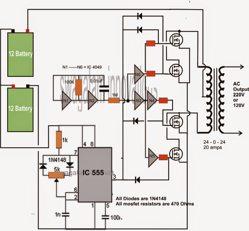
This inverter circuit functions on the principle of converting a pure dc signal into a free running square waveform, through the help of a multivibrator circuit operating in astable mode.
They can convert 12vdc from battery to 220vac or 120vac to apply small light bulbs or lamps max 10 watts. This is achieved by chopping off the excess rms voltage of the astable square wave signal from the multivibrator circuit. So, in today’s tutorial, we will take a look into a step by step process on how you can build a simple 12v to 220v inverter circuit using two irfz44 mosfets. Ic 555 timer is an ever green integrated circuit which has tons and tons of applications;
500w high power inverter circuit diagram.
All you need is a good soldering skills , a little bit […] 100watt inverter circuit inverter circuits are accompanied by the easiest circuits to produce develop for newbies here is the circuit diagram of a genial 100 watt inverter using ic cd4047 and mosfet irf540. Image of the pcb layout of this high power inverter circuit diagram is given. Inverter circuit diagram using sg3525 and mosfet a 250w pwm inverter circuit built around ic sg3524 is shown here.
It contains all the necessary features and libraries that will suffice you in your diagram making.
Simplest inverter using hybrid mosfets and igbts with unipolar pwm to scientific diagram. For a vdd of 3v, 5v, 7v, sketch the input waveforms required to test the functionality of the cmos inverter. If you think that this circuit is not good enough. To ensure 100% safety for the mosfets in the charging mode and while using the body diodes with the transformer ac, the mosfet gates must be held at the ground potential, and completely.
220v inverter circuit using irfz44 mosfet simple 100w with fet irf540 12v to 230vac rangkaian dc ke ac panduan 500w power circuits electrical4u 555 h bridge 4 n what is an diagram 7 you can high voltage easy 150 w full 100 watts working and for newcomers watt 500.
Bc548 / any npn transistor x 2; Also 500w inverter circuit for you. This is the complete circuit diagram of a 1250va/24v mosfet inverter with battery charger. The circuit is simple low cost and can be even assembled on a veroboard.
Below is also component layout/pcb layout of this schematic diagram.
Simple 12v to 230vac inverter circuit mosfet diy electronics. The pcb layout of this circuit diagram is below. Download a better high resolution circuit diagram here. Simplest inverter using hybrid mosfets and igbts with unipolar pwm to scientific diagram.
The circuit is simple low cost and can be even assembled on a veroboard.
This simple low power dc to ac inverter ( dc to ac converter) circuit converts 12v dc to 230v or 110v ac. Find every electronics circuit diagram here, categorized electronic circuits and electronic projects with well explained operation and how to make it procedure and then new circuits every day, enjoy and discover electronics. We can make a very reliable inverter using ic 555 and mosfets. 1.5v to 220v simple inverter circuit;
The following diagram shows a practical design set up for implementing mosfet body diodes as a rectifier for charging an inverter battery, with relay changeover switches.
This inverter circuit diagram which can change the voltage 12 volt dc to 230 volt ac.scheme inverter circuit is capable of removing power output up to 3000 watt, for beginners as possible to assemble a circuit schematic this inverter will be a little complicated and confused, but if. Pwm inverter circuit diagram using ic sg3524 and mosfet. In circuit use irf540 mosfet. The oscillator stage, the driver stage and the full bridge mosfet output stage.
Simple 100w inverter circuit full of zip and circuit diagram.
Simple mosfet inverter circuit diagram. The circuit diagram of mosfet inverter. You do not have it now. This voltage should be suitably derived from one of the batteries which are being incorporated for driving the inverter circuit.
Here are a few related posts you may find helpful, too:
Now you know how a basic inverter works. Inverter circuits are among the easiest circuits to build for newbies. By doing simple modification you can also convert 6v dc to 230v ac or 110v ac. Use edrawmax for circuit diagram creation.
This is a must try inverter for beginners and first time diy inverter makers among hobbyists.
Simple inverter circuit using ic 555.