What is not gate (inverter) simple led flasher circuit with 555 timer. Cd4047 is a low power ic capable of operating in either in astable or monostable mode. Here it is wired in astable mode.
50W 220v Inverter Circuit Diagram Using ic 4047 50w
March 26, 2018 at 7:37 am.
Retrofit toilet cistern overflow monitor t.k.
100 watt inverter using ic 4047. The 4047 ic is one of the popular ic with low power consumption. Square wave generator using cd4047. Here is a 100 watt inverter circuit using minimum number of components.
Cd4047 requires only 2 devices, resistor, and capacitor only.
In simpler words, the basic function of the inverter circuit is to generate the oscillation. Inverter circuits vary with the power requirements and been widely available all over the internet. My sources you are so cool! The ic1 cd4047 wired as an astable multivibrator produces two 180 degree.
It has a wide range of input voltage (3v to 18v) and dc current input is up to ±10ma with a high operating temperature range of −55°c to +125°c.
Makes different inverter circuit projects. Simple inverter circuit diagram 12v to 220v. Simple inverter circuit using cd4047 and uln2003. Inverter circuits are provides ac power output using available dc voltage from battery, some times we need low power output enough to drive a small electric light bulb or something those are not require pure ac power.
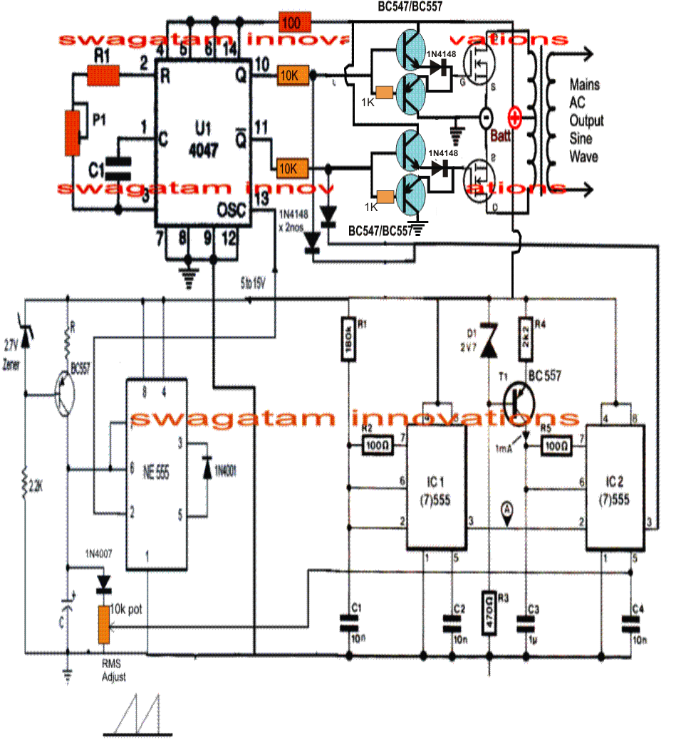
One typical simple square wave inverter application using the ic 4047 can be witnessed below:
The circuit output is high voltage and can cause electrocution. I am using the attached image cct for square wave inverter but i dont get any output.i have the simulative model of cd 4047 and design file of proteus as well attached kindly check it and help i have to submit it soon. A compact and portable 12v solar power inverter circuit that will keep away darkness. 4047 circuits (11) browse through a total of 11 4047 circuits.
Before going into detail we should know about ic 4047.
We have collected these discussions here and presenting it. Simple inverter 12v to 220v with. Here is a 40 watt inverter circuit which uses ic cd4047b and some transistors to perform the desired action. Such as we have an article about the pure sine wave inverter circuit.
And more importantly, it has a duty cycle at 50% in a symmetrical standard, no need for additional equipment.
If you’re a complete beginner to electronics, know that an inverter is a circuit that is designed to convert the direct current (dc) power to alternating current (ac) power. It works by charging a capacitor (c2) through a resistor (rv1) as in every astable multivibrators. In summary, the ic works solely on two modes specifically. In this topic i will tell you how to ic inverter using proteus(inverter circuit in proteus).
11 thoughts on “220v 50w low power inverter circuit” my sources.
The components we using are follows. 100 watts inverter circuit using cd4047 & irf540. First of all we have to select the components from the library. The formula for calculating the frequency or the rc components are:
Variable resistor (rv1) is provided for.
We should use 4047 ic in astable mode to generate a square wave. Frank donald april 7, 2014 2 comments. It is therefore suitable for generating a set frequency in. F = 1/8.8rc at pin#10 and pin#11
We only need a couple of resistors and capacitors with this multivibrator ic to generate a square signal.
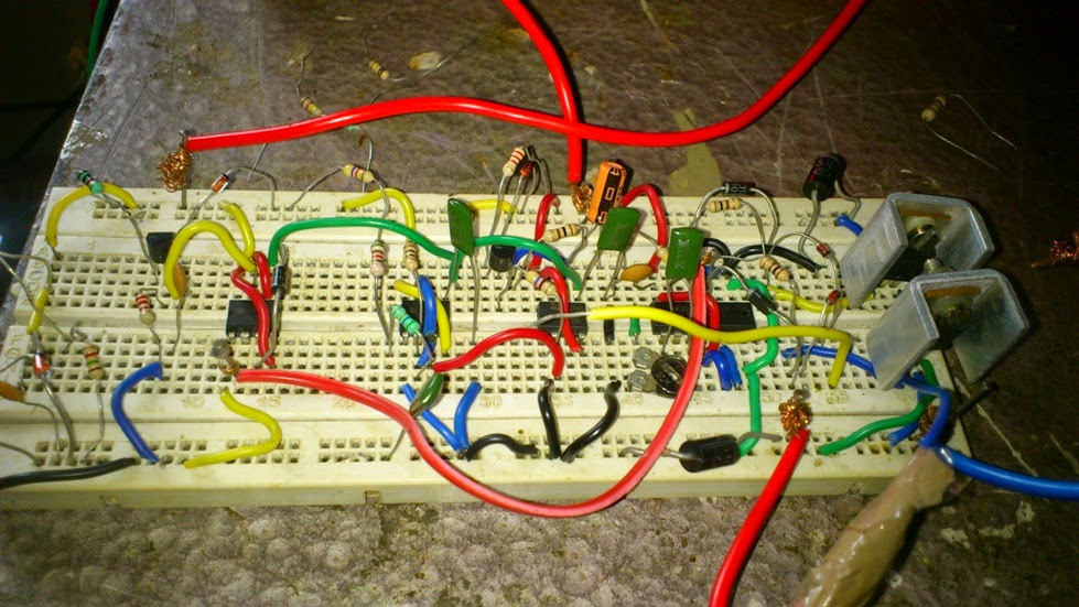
Pure sine wave inverter using 4047 with pulse width modulation (pwm) on a breadboard, design by swagatam majumdar.modified here for 200 watts.this video woul. I don’t believe i’ve read anything like this before. Low cost 500w inverter circuit using 2n3055. You can adjust the frequency by adjusting the potentiometer.
I think it is quite difficult to make a decent one like this with further less components.here we use cd 4047 ic from texas instruments for generating the 100 hz pulses and four 2n3055 transistors for driving the load.
Inverter circuit diagram using cd4047 simple inverter circuit using cd4047 working. Do not build this inverter if you have little or no idea in electrical engineering. This is a circuit diagram for the square pwm generator. A square wave is a pwm signal with equal width of logic high and low signal.


