In digital logic circuits, binary arithmetic & switching or logic function’s mathematical manipulation are best performed through the symbols 0 & 1. First implementation of truth table allows the output to go flotaing without attaining a high or low. Inverter (not gate) schematic symbol
Floatinggate analog inverter circuit with corresponding
Both symbols have the equation q = not a.
The delay of a signal is always measured with respect to a reference signal.
Q = ( a ∧ b ) ∨ ( c ∧ d ) ¯. The circuit symbols are the same but with a small circle on the output, indicating the inversion of the logic level. Single line symbols electrical symbols used to represent various electrical devices for usages in electrical schematic design. Jic / nfpa sample drawing.
Ab becomes ¯¯¯¯¯¯¯¯abab¯, a + b becomes ¯¯¯¯¯¯¯¯¯¯¯¯¯¯¯a+ba+b¯, and so on.
To build a circuit you need a different diagram showing the layout of the parts on breadboard (for temporary circuits), stripboard or printed circuit board. Converter dc / dc convertion of direct current to direct current + info : Inverter dc to ac converter + info: Generic symbol rectifier ac to dc converter converter dc / dc convertion of direct current to direct current rectifier inverter coverter ac / ac convertion of alternating current to alternating current rectifier inverter inverter dc to ac converter.
When long lines (interconnects) or chip outputs must be driven buffer circuits.
Add a dc source by selecting ic_library sources library dc. The difference in symbols is conceptual, it's to aid understanding. To create the schematic of an inverter and then to generate its symbol. Simulation of the designed unit is covered in a separate tutorial.
Nmos inverter m1 m2 m3 x v out v in figure 1.
The first symbol is a classical inverter. An inverter is a logic gate that has only one input, it outputs the opposite logic state of its input. Rectifier ac to dc converter + info : Its symbol is simply a triangle, with no inverting “bubble” on the output terminal:
The not gate is also called an inverter buffer or simply inverter.
When the control signal c is high the output y is the inverted input signal x. The notation of the logic operation of inverter can be expressed by: (2) build the schematic from g. In symbol generation window, modify the pins specifications and click ok.
Ic 555 timer is an ever green integrated circuit which has tons and tons of applications;
As youmay have noticed, the signal 'v(vout)'has undershoots and overshoots. Integrated circuit inverter jack, coaxial. The output changes to the inverse of the input. Highlight the dc source, right click mouse, properties edit to modify the voltage value of the source from 1v to 3.3v.
Connect the positive node of the dc source to vdd symbol and negative terminal to the ground symbol.
Circuit symbols are used in circuit diagrams showing how a circuit is connected together. Nmos inverter (1) create a cell named rec 2 nmos inv in virtuoso. It is symbolized by a triangle with a circle at its output terminal. In schematic window of inverter, go to.
The boolean symbols change by placing a bar over the original expression:
We can make a very reliable inverter using ic 555 and mosfets. If the input logic is zero (0) then the output will be high (1) whereas, if the input logic is one (1), then the output will be low (0). Simple inverter circuit using ic 555. The circle (often called a 'bubble') represents inversion.
In cell view from cell view window, verify the library name and cell name.
Power converter generic symbol + info : Create → cell view → from cell view. 1 with the channel lengths equal to 100nm, w m 1 = wn, w m 2 = k * wn, w m 3 = wn. The inverter is also called not gate.
Software like edrawmax has all features to make a perfect circuit diagram.
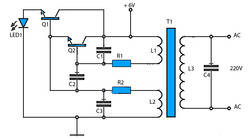
This is a must try inverter for beginners and first time diy inverter makers among hobbyists. The cmos inverter truth table is shown above. The actual layout of the components is usually quite different from the circuit diagram. Remember to connect the bulks of the transistors.
Coverter ac / ac convertion of alternating current to alternating current generic symbol + info:
Out pins of the inverter symbol as shown in the figure. Since we are interested in the delay of the inverter, choose 'v(vout)' for 'signal' and 'v(vin)' for 'ref. This allows other devices connected on shared bus to drive the bus.


