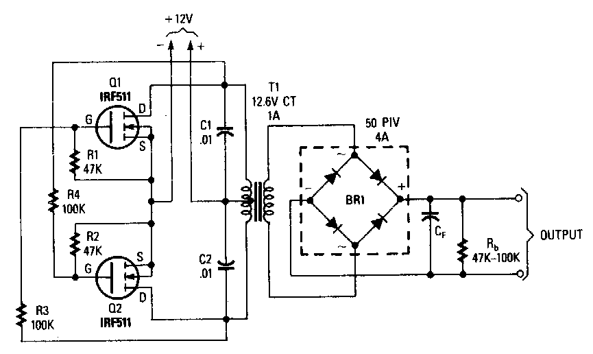
Change the value of r1 from 4.7 kω to 20 kω and note the resulting changes This is the complete circuit diagram of a 1250va/24v mosfet inverter with battery charger. After completing the circuit, bring a fully charged 12v 7ah battery for testing.
Power MOSFET Inverter
The transfer characteristics of an ideal inverter is shown below.
The breadboard schematic of the circuit above is shown below.
The transformer i use 2a current and 12v input at output power more than 100 watts. In the event of a power failure, an inverter is very useful as a backup power unit, and if optimally charged, will also allow you to use your pc, tv, lights, power tools, appliances, and other electrical conveniences atop. The designed system generates 223v square signals at each phase from a 12v battery through switching of three stages of power mosfets using pulse width modulation (pwm) signals at their gates from an arduino uno. Thus to obtain a positive voltage (+v) across the load, the transistors q 1 and q 2 are turned.
So this is just a basic inverter circuit built using a mosfet transistor.
An inverter circuit can convert a dc signal of a nominal voltage strength (9v, 12v) to a substantially higher ac signal of the desired voltage level (220v). The arrangement of the inverter consists of four transistor, (mosfet or igbt).to obtain an ac waveform at the output, the transistors are turned on and off in pairs of q 1, q 2 and q 3, q 4. Inverter circuits being the favorites with these devices, we would be discussing one such design incorporating mosfets for powering the. • complementary mos (cmos) inverter analysis makes use of both nmos and pmos transistors in the same logic gate.
Inverter circuits are among the easiest circuits to build for newbies.
The inverters can be applied directly to the design of logic gates and other more complex digital circuits. The inverter is an electronic device used to convert direct current (dc) into alternating current (ac). Here, mosfet is active load and inverter with active load gives a better performance than the inverter with resistive load. + all static parameters of cmos inverters are superior to those of nmos inverters + cmos is the most widely used digital circuit technology in comparison to other logic families.
Upload the code to arduino first and start constructing the circuit.
Inverter circuit is one of the fundamental building blocks in digital circuit design (not to be confused with a power inverter). Here are a few related posts you may find helpful, too: Mosfets are mostly used in cmos circuits. The inverter circuit we will build with a transistor is shown below.
Here the 12v to 220v inverter based mosfet irfz44.
Whatever signal we feed into the input gets inverted to the opposite logic state at the output. When we talk about inverter circuits involving power outputs, mosfets imperatively become a part of the design and also the main component of the configuration, especially at the driving output ends of the circuit. In circuit use irf540 mosfet. The lm324 is simply too slow to drive a mosfet gate in any inverter operating at a reasonable speed.
N1, n2, n3, n4 not gates from the ic 4049 are arranged as a voltage doubler circuit, which generates about 20 volts from the available 12v supply.
1 shows single phase bridge inverter with resistive load. Bc548 / any npn transistor x 2; Note the (vin, vout) coordinates for any key corner points in the characteristics. Simple 12v to 230vac inverter circuit.
Uyemura, “introduction to vlsi circuits and systems,” 2002.
The pcb layout of this circuit diagram is below. How to make simple inverter circuit diagram within 5 minutes; Once the arduino booted you will hear a beep. Turn the “switch 1” first let the arduino boot.
Sketch the vtc in your notebook, ticking off each axis in 1 volt increments to match the scale factors used on the oscilloscope.
In the electronics or logic design subject the inverter is also known as the not gate which does nothing but logical negationelaborating more the inverter or. Download a better high resolution circuit diagram here. A circuits and systems perspective,” 2011. 1.5v to 220v simple inverter circuit;
The circuit diagram of mosfet inverter.
Mosfet driver circuit which forms a logic inverter gate. Now you know how a basic inverter works. Here, mosfet is an active load and inverter with active load gives a better performance than the inverter with resistive load. The alternating current is a current that consistently changes its magnitude with respect to time.
Inverter with n type mosfet load the main advantage of using mosfet as load device is that the silicon area occupied by the transistor is smaller than the area occupied by the resistive load.
This current flows only in one direction. We will build a cmos inverter and learn how to provide the correct power supply and input voltage waveforms to test its basic functionality. There are many advantages of cmos, with the biggest being zero standby power consumption, at least ideally.


