This is component layout or pcb layout of this 500w inverter circuit. A power inverter is an electrical device which “inverts” a dc source (typically 6v, 12v, 24v or 48v battery) to a standard 230v ac at 50 hz or 120v ac at 60 hz or in other words a power inverter takes a dc input and outputs ac at a higher voltage than the input. The cd 4047 ic is configured in this 12 volt to 220 volt inverter with the aid of several components like.
Simple Solar Inverter Circuits for Students
The design will be needed in higher schematics including a testing
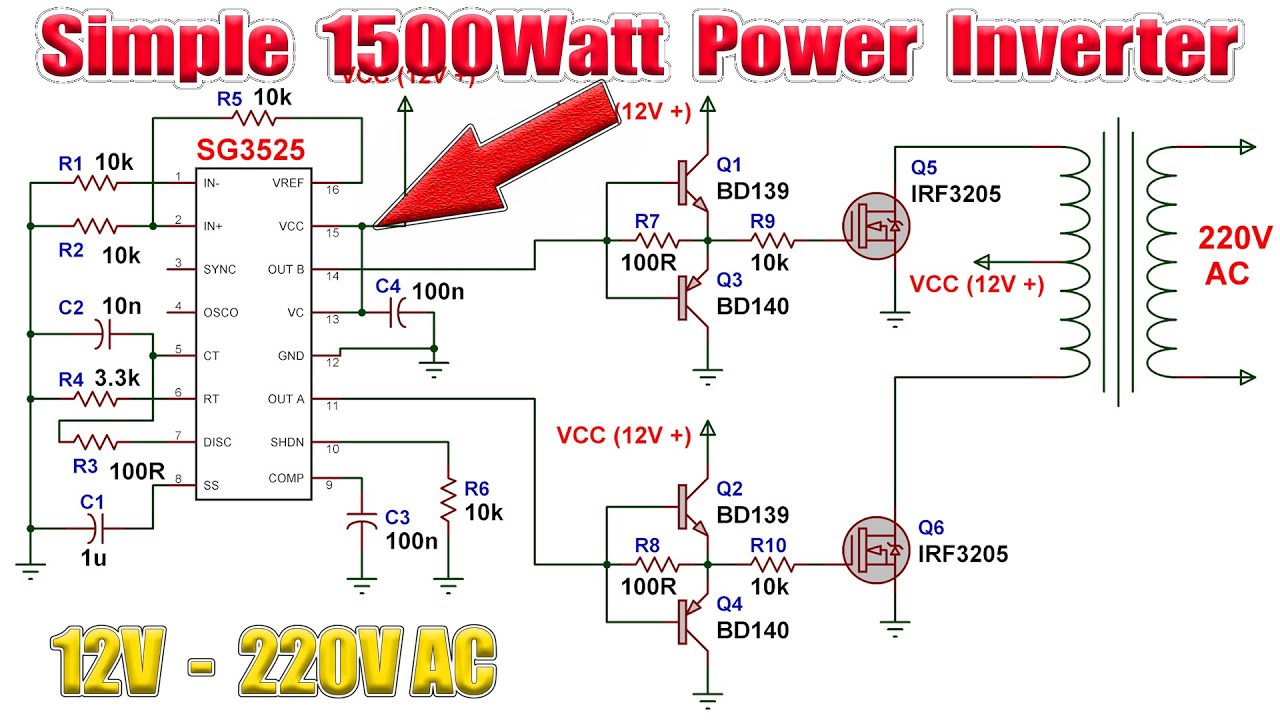
9/06/2015 · 230v, 50hz, 1.5kva, full bridge pure sine wave inverter circuit using sinusoidal pulse width modulation.
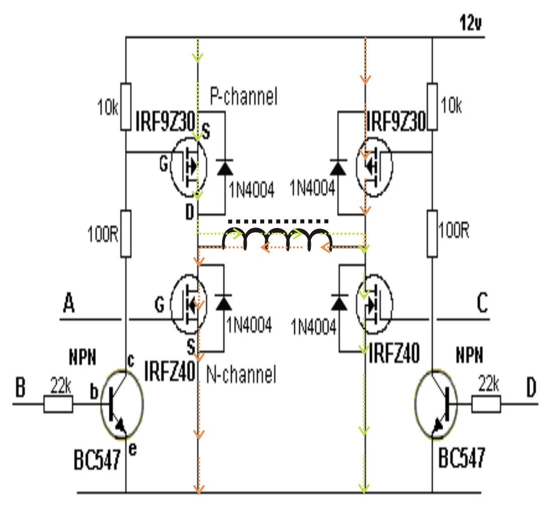
A pure sine wave, after passing it through an lc filter. All the four devices may be n channel type or with two n channel and two p channel depending upon the external driver oscillator stage that's being used. Figure below shows the circuit diagram of cmos inverter. Sf6 circuit breaker control circuit diagram pdf.
Inverter sub panel wiring diagram.
1000w 12v dc home power inverter circuit board design. The home inverter overall structure is, downside is a large cooling plate. I have included circuit diagram using igbt, pic18f886 circuit diagram, assembly language program for pic16f886 and hex file in pdf format. For example, a 50 percent duty pulse.
On these properties, it can be used to make a power inverter.
The operation of cmos inverter can be studied by using simple switch model of mos transistor. Inverter ac wiring diagram pdf. 555 is a timer ic which is used to generate time delay. There are many basic electrical circuits for the power.
R2, r3, r4, r5 = 1k, t1, t2 = irf540;
The inverter is a device that used to transform the dc to ac in the electrical system. A full bridge inverter circuit consists of four transistors or mosfets arranged in a configuration resembling the letter h. An inverter has a limited power output capacity and also has a limited operating time i.e. The circuit representation of the inverter.
The circuit diagram shown above is the tested 12v dc to 220v ac inverter circuit.
Ups inverter diagrams pdf free 3000w power 12v to 230v digital circuit diagram 4 simple uninterruptible supply sinewave using pic16f72 homemade solar m 100 watt offline engineering projects electronic abc home facebook sine wave build 200w 500 with battery circuits 2000w homage schematic microtek how an works. Home » design » 1000w 12v dc home power inverter circuit board design. R1 = 220k pot, needs to be set for acquiring the desired frequency output. Microtek inverter circuit diagram pdf electrical learner.
This is the circuit diagram of 500w high power inverter market kit.
The circuit in this article shows you a simple way to build a 12v to 230v inverter circuit diagram of 100watt power using 555 ic. How to build 200w inverter circuit diagram project eleccircuit com. Introduction this report focuses on dc to ac power inverters, which aim to efficiently transform a dc power source to a high voltage ac source, similar to power that would be available at an electrical wall outlet. Refrigerator inverter compressor wiring diagram.
House wiring with inverter connection a s solution diagram diy charging car battery home circuit for 100 watt how an works working of to connect at your simple diagrams solar panel facebook china parrael easy made you can make in own sine wave full schematic typical 7 circuits build 200w db help.
C1 = 0.01uf, c3 = 0.1uf; Parts list for the above explained 150 watt inverter circuit diagram: It uses 2 power irfz44 mosfets for driving the output power and the 4047 ic as an astable multivibrator operating at a frequency of around 50 hz. This is the complete circuit diagram and for pcb layout of.
Ac compressor wiring diagram pdf.
This is done using the cadence composer. The main use of dc in the solar system, batteries cells since these generate dc. This power inverter is designed for 12v dc, but also can be connected to 24v dc, my goal is 800 watt, strive to 1000 watt pure sine wave output. Inverter air conditioner circuit diagram pdf.
The common use of dc is in solar systems where generation occurs in dc so inverters are used to convert dc to ac.
The main function of an inverter is to convert dc to ac.