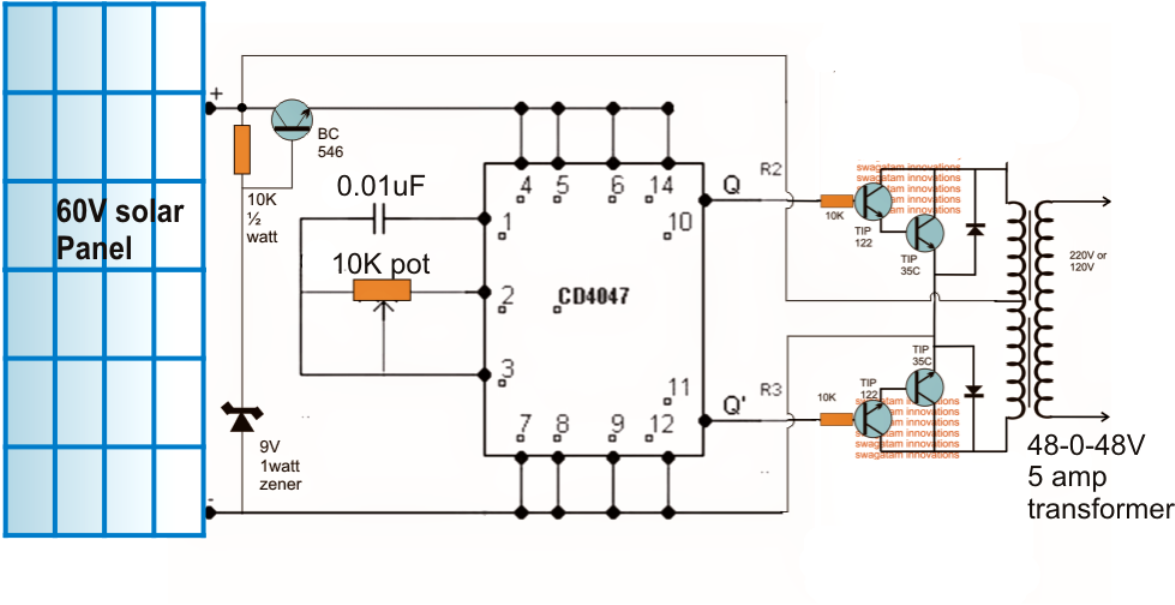
Multiple inverters and solar panel circuits? Calculation & design of solar photovoltaic modules & array how to design a solar photovoltaic powered dc water pump? The pulse repetition rate of ic1 is determined by the value of 4.4xc2xr2.
10KVA SolarGrid Inverter Changeover Circuit with Low
The inverter circuit utilizes 12v solar panels which generates around 17v when there is good sunshine.
However, it greatly increases the reliability and efficiency of the total system.
Connect inverter to battery bank. Designing a solar inverter circuit essentially requires two parameters to be. The solar inverter circuit is used to power household appliances and any other electrical devices by converting solar energy to electrical energy. The inverter circuit provides an alternating current output (ac) from the power supply battery, but the battery needs to be supplied with a constant dc supply for a charge.
Attention to safety rules when installing our new solar photovoltaic system is very important and commitment with such rules will protect us from many troubles and dangerous matters we may face in the future.
It also converts and steps up low voltage battery power to high voltage ac mains levels. It also has all the functions to construct a regulated power supply. The three units are connected through a solar regulator circuit that distributes the power to the respective units after appropriate regulations of the received power from the solar panel. The main circuit of solar on grid inverter is presented in the following diagram.
Before adding inverter power to the breaker panel, you should:
Here sg3524 chip is the primary component to build a solar inverter. It has complete circuitry for pulse width modulator (pwm) control. Sg3524 chip offers improved performance and requires less external parts while building switching power supplies. Step up transformer (output stage) pv solar inverter circuit diagram.
Also, another main application of inverters is on the power consumption and grid.
Smaller solar arrays may use a standard string inverter. Step by step tutorial on how to connect your solar panel to the battery and inverter. Turn off the inverter power button too. In both the case the inverter works without depending on mains utility grid power.
Ic1 generates cmplementary squarewave signals at its output pins 10 and 11.
2) read up on materials from the manufacturers of the solar panels and inverters, 3) consult your sonoma or marin county electrician for expertise and knowledge of local california electrical codes. Capacitor c2 and resistor r2 are timing components. Consult an electrician if you do not feel comfortable handling these wires. The inverter draws the dc from the solar panels, batteries, and fuel cells and converts them into ac electricity.
You may need to connect multiple 12v solar panels in parallel to generate sufficient current to the inverter depending on your power needs at the output.
The ac input power must provide these circuits, so only the ac output can be accessed from this circuit. Photovoltaic solar inverter circuit constructed with five different stages. 1) conduct research to make sure you understand all the home solar power basics. It can be encapsulated as handheld inverter.
Shut off the circuit breaker main power.
Solar inverter circuit constructed with few different stages. The following assumes you have some experience installing electrical components. Connect your solar panels, solar charge controller and battery bank. Unless you either generate 100% of your electricity from your pv, or alternatively if your grid power is 100% either hydro or re, the curve rapidly slants toward using gas for heat generating tasks if it is available.
Inverter circuit gives alternating current (ac) output from battery power source, but the battery requires constant….
The problem with that connection is that the solar panel output voltage can be higher than the inverter’s input voltage, and in this case, the inverter won’t work. Assuming the voltage to be 36 and the current to be 10 amps from the solar panel, the inverter is selected with an input operating voltage of 24 volts @ 6 amps, providing a total. When they do, a string of solar panels forms a circuit where dc energy flows from each panel into a wiring harness that connects them all to a single inverter. The solar powered inverter circuit, optimised for cfl loads, uses ic cd4047b (ic1) as a freerunning astable oscillator.
The circuit will function as a micro inverter circuit, meaning it is intended to be connected to a single solar panel.
If connected in parallel to many solar panels, our design should be able to drive actual Inverter circuit (switching pulse oscillator) switching device; If your home runs on solar power, you can easily connect a circuit breaker to the inverter. The solar panel power is either directly used for operating the inverter or it's used for charging the inverter battery.
Arduino projects blog do it yourself solar circuits.
Solar power system electrical circuits safety. Here an inverter is used to convert the dc electricity from the panels into the ac power required in your home and feed excess power in ac format back into the grid. The inverter’s power will determine by the input voltage, output voltage, and frequency depending on the design of the inverter. Regulator / battery chagerg 3.
My point is that for heating, nat.
The solar panels generate electricity that supplements the power you receive from the grid. The inverters are required stable flows of electricity to transform the power from the current source. If your solar system output voltage is lower than the inverter’s input rating, then sure, you can connect the inverter directly to the solar panel. How to make solar inverter circuit.
When a dc to ac inverter is operated through a solar panel, it is called a solar inverter.
The answer is yes and no, depending on your solar system’s size. Gas if available is fundamentally more efficient. Pv solar inverter circuit diagram. This is a slightly more expensive option for a solar system;
Solar inverter circuit gives alternating current (ac) output from battery power source, but the battery requires constant dc power supply to get charge, so the every inverter circuit contains rectifier &battery charger controller segment.
Safety rules will guide in making our whole solar system to be. Stages of pv solar power inverter. The device converts sun rays into direct current at lower potential levels. In other words, this type of inverter has unique functions made for photovoltaic arrays.