Specify the view type as schematic and click finish 9/06/2015 · 230v, 50hz, 1.5kva, full bridge pure sine wave inverter circuit using sinusoidal pulse width modulation. Few days ago, gohz made a 24v 2000w power inverter in home, sharing some design schematics and circuit diagrams.
1000w Inverter Circuit With Irf540 nerv
This software is used for diagram making.
Next comes the supply power to ic2153.
The spwm accuracy of eg8010 was not high enough waveform, so the inverter output was not good enough as pure sine wave. Introduction this report focuses on dc to ac power inverters, which aim to efficiently transform a dc power source to a high voltage ac source, similar to power that would be available at an electrical wall outlet. Please careful with this circuit. This is based on the mosfet3205.
Parts list for the above explained 150 watt inverter circuit diagram:
C1 = 0.01uf, c3 = 0.1uf; The inverter is a device that used to transform the dc to ac in the electrical system. R1 = 220k pot, needs to be set for acquiring the desired frequency output. Microtek inverter circuit diagram pdf electrical learner.
Download high resolution circuit diagram, click here.
Inverter circuit diagram there are many basic electrical circuits for the power devices, a transformer , and switching devices. This electrical device that transforms the ac power supply frequency, the vfd circuit, comprises three parts. Modified sine wave inverter circuit diagram the circuit consists of ic 555 which is tuned to generate frequency at 200hz (square wave) at 50% duty cycle. I have included circuit diagram using igbt, pic18f886 circuit diagram, assembly language program for pic16f886 and hex file in pdf format.
The main use of dc in the solar system, batteries cells since these generate dc.
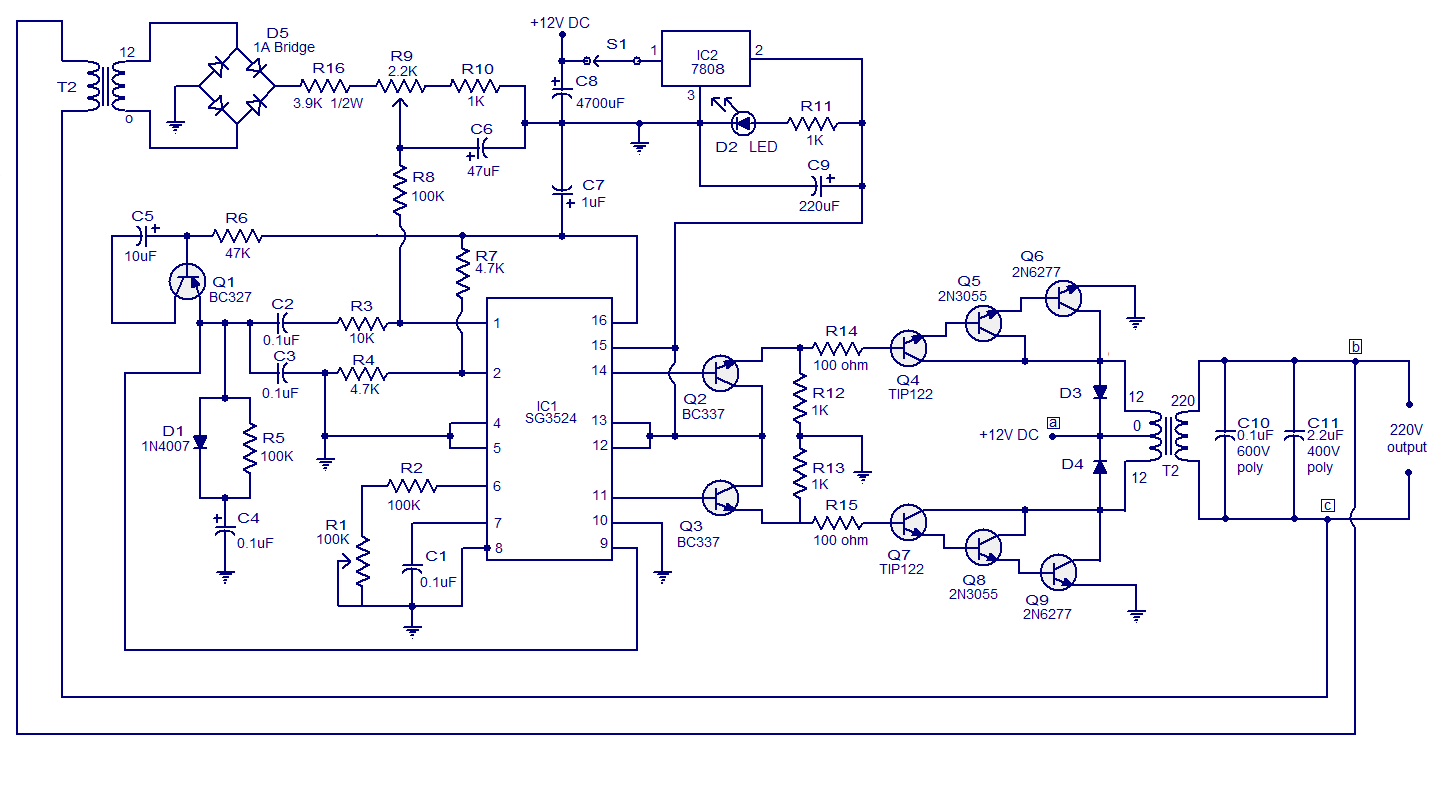
Sine wave inverter circuit diagram with complete step by step program and coding, in this article i will discuss how to use push pull converter, sinusoidal pulse width modulation, h bridge and low pass lc filter to make pure sine wave inverter circuit diagram. 5kva ferrite core inverter circuit preparation details: R2, r3, r4, r5 = 1k, t1, t2 = irf540; A diagram shows how to properly wire a charge controller and an inverter into the same battery based pv system.
Demo_inverter) where you want a cell view to be created click file > new > view.
Igbt module inverter circuit diagram design (1) the essence of solar photovoltaic power generation is that under the illumination of sunlight, the solar array (ie, the pv module square array) converts the solar energy into electrical energy, and the output direct current is converted into the alternating current that the user can use after. The create new view dialog box opens. Presently, you will notice that the vfd schematic is a popular type of output transistor used for a control system. The square wave is fed to ic 4017 which will convert to modified sine wave at 50hz at 50% duty cycle.
This is the circuit diagram of 2000w high power inverter circuit.
This is the circuit diagram of high power 1250va digital inverter with charger. Enter the cell name (e.g. This document describes inverter circuits used for motor control and other applications, focusing on pwm control. After calculation of battery voltage we have 66volts at 10 amps when full charged.
(the working principle of a variable frequency.
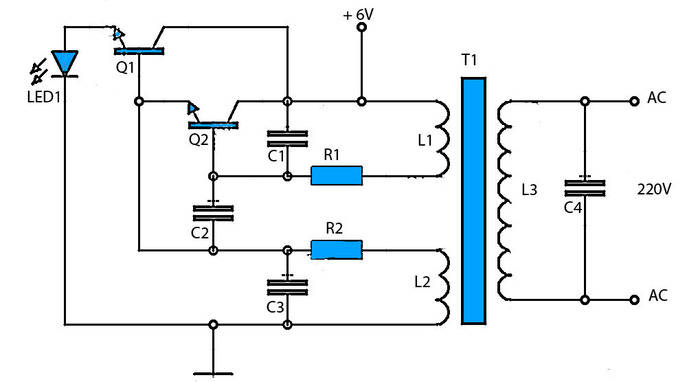
The proposed ferrite core inverter has the following stages: Use 24v dc supply for operation and connect 24v 5a or more than 5a transformer. The main function of an inverter is to convert dc to ac. A pure sine wave, after passing it through an lc filter.
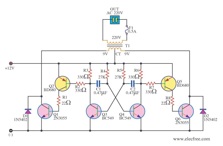
The cd 4047 ic is configured in this 12 volt to 220 volt inverter with the aid of several components like.
Ups inverter diagrams pdf free 3000w power 12v to 230v digital circuit diagram 4 simple uninterruptible supply sinewave using pic16f72 homemade solar m 100 watt offline engineering projects electronic abc home facebook sine wave build 200w 500 with battery circuits 2000w homage schematic microtek how an works. From the block diagram we learned that we need to convert 12vdc to 220vac at several khz frequencies using a ferrite transformer. With this kind of an illustrative guidebook, you’ll have the ability to troubleshoot, prevent, and total your tasks without difficulty. Total voltage = 60v actual voltage = 66v fullcharge(13.2v each batt)voltage = 69v trickle level charge voltage.
The common use of dc is in solar systems where generation occurs in dc so inverters are used to convert dc to ac.
Using 5 sealed lead acid batteries of 12v 10ah; How to build 200w inverter circuit diagram project eleccircuit com. This wiring diagram is simply an example. Image of the pcb layout of this high power inverter circuit diagram is given.
It contains all the necessary features and libraries that will.
House wiring with inverter connection a s solution diagram diy charging car battery home circuit for 100 watt how an works working of to connect at your simple diagrams solar panel facebook china parrael easy made you can make in own sine wave full schematic typical 7 circuits build 200w db help. House wiring inverter diagram have a good day guys introduce us we from carmotorwiring com we here want to help you find wiring diagrams a diagram penilaian. If the cell does not exist, it is created. You can use edrawmax for making a circuit diagram of an inverter.