By doing simple modification you can also convert 6v dc to 230v ac or 110v ac. This is based on the mosfet3205. If the cell does not exist, it is created.
1000w Inverter Circuit With Irf540 Circuit Diagram Images
Using 5 sealed lead acid batteries of 12v 10ah;
The dead zone time was a bit.
Specify the view type as schematic and click finish C1 = 0.01uf, c3 = 0.1uf; This is the circuit diagram of 2000w high power inverter circuit. House wiring with inverter connection a s solution diagram diy charging car battery home circuit for 100 watt how an works working of to connect at your simple diagrams solar panel facebook china parrael easy made you can make in own sine wave full schematic typical 7 circuits build 200w db help.
With this kind of an illustrative guidebook, you’ll have the ability to troubleshoot, prevent, and total your tasks without difficulty.
Parts list for the above explained 150 watt inverter circuit diagram: The create new view dialog box opens. This simple low power dc to ac inverter ( dc to ac converter) circuit converts 12v dc to 230v or 110v ac. Enter the cell name (e.g.
The dc alteration to an ac can be attained by stored energy within the dc source like the battery.
On these properties, it can be used to make a power inverter. Total voltage = 60v actual voltage = 66v fullcharge(13.2v each batt)voltage = 69v trickle level charge voltage. Demo_inverter) where you want a cell view to be created click file > new > view. Introduction this report focuses on dc to ac power inverters, which aim to efficiently transform a dc power source to a high voltage ac source, similar to power that would be available at an electrical wall outlet.
Inverter circuit gives alternating current (ac) output from battery power source, but the battery requires constant dc supply to get charge, so the every inverter circuit contains rectifier and battery charger segment.
After calculation of battery voltage we have 66volts at 10 amps when full charged. To this end, the cmos inverter is in several electronic devices while offering data around small circuits. Next comes the supply power to ic2153. The following diagram is the basic design diagram of inverter circuit.
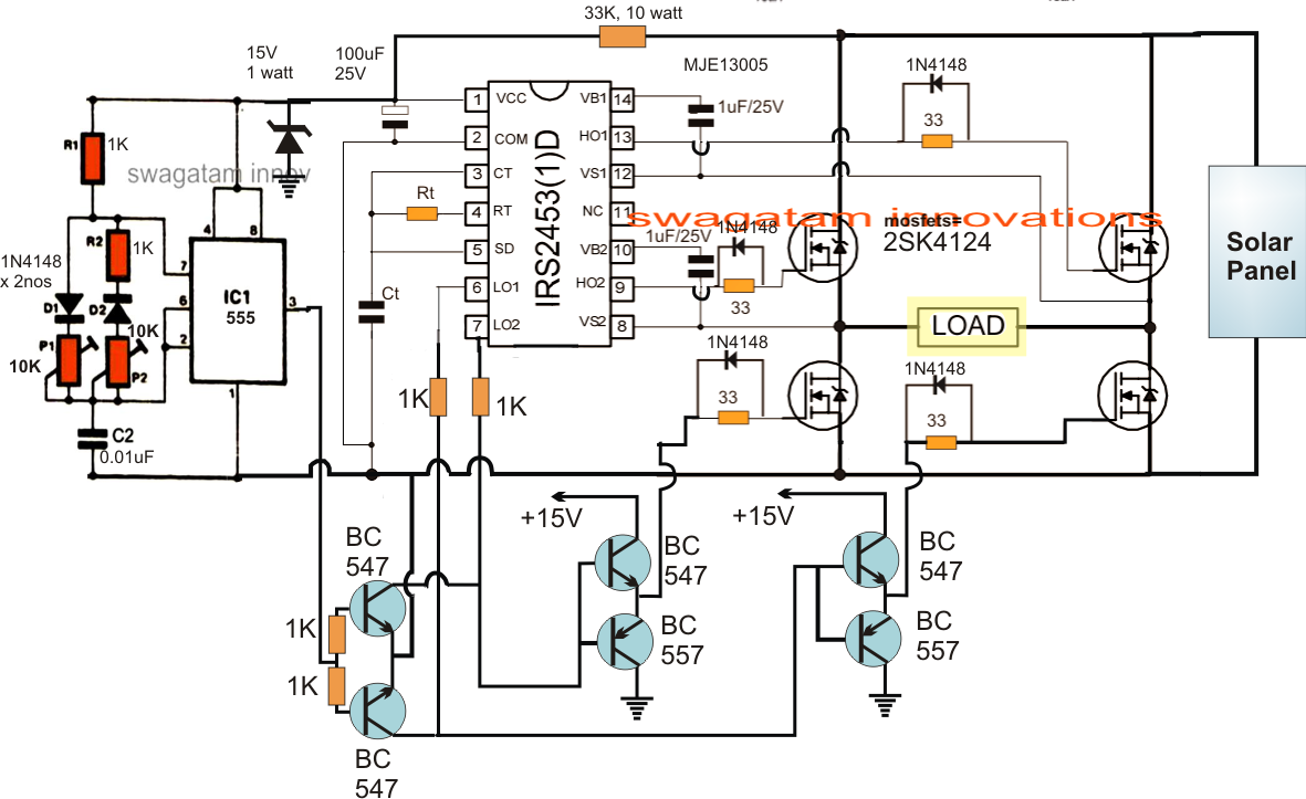
The main circuit of solar on grid inverter is presented in the following diagram.
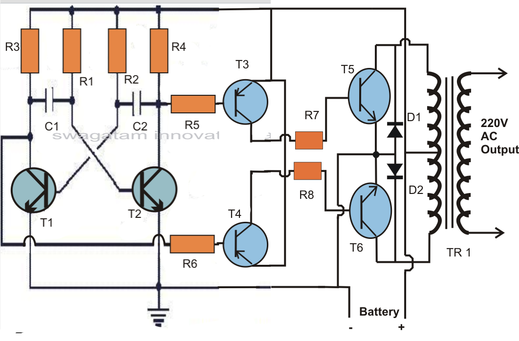
R1 = 220k pot, needs to be set for acquiring the desired frequency output. Thus to obtain a positive voltage (+v) across the load, the transistors q 1 and q 2 are turned. 555 is a timer ic which is used to generate time delay. This basic inverter circuit can handle up to 1000watts supply depends the t1, t2 and transformer used.
The circuit will convert 12v dc to 120v ac.
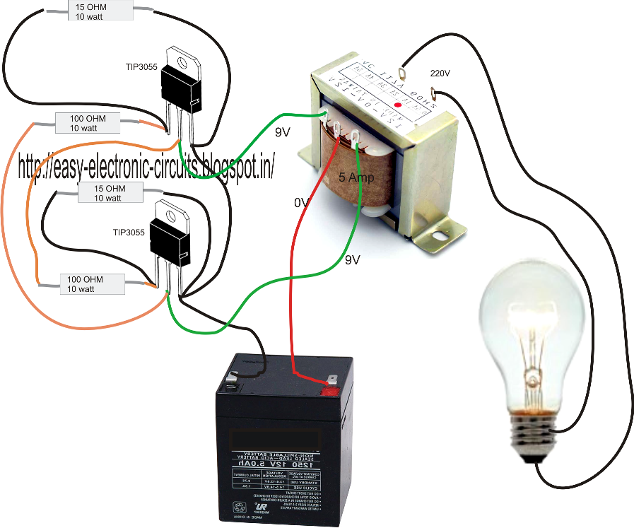
Inverter circuit diagram there are many basic electrical circuits for the power devices, a transformer , and switching devices. They can convert 12vdc from battery to 220vac or 120vac to apply small light bulbs or lamps max 10 watts. This document describes inverter circuits used for motor control and other applications, focusing on pwm control. The square wave is fed to ic 4017 which will convert to modified sine wave at 50hz at 50% duty cycle.
Simple low power inverter circuit | 12v dc to 230v or 110v ac | diagram using cd4047 and irfz44 power mosfet.
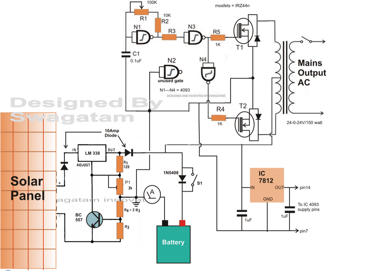
Modified sine wave inverter circuit diagram the circuit consists of ic 555 which is tuned to generate frequency at 200hz (square wave) at 50% duty cycle. The spwm accuracy of eg8010 was not high enough waveform, so the inverter output was not good enough as pure sine wave. It is hard to find equipment. The arrangement of the inverter consists of four transistor, (mosfet or igbt).to obtain an ac waveform at the output, the transistors are turned on and off in pairs of q 1, q 2 and q 3, q 4.
How to build 200w inverter circuit diagram project eleccircuit com.
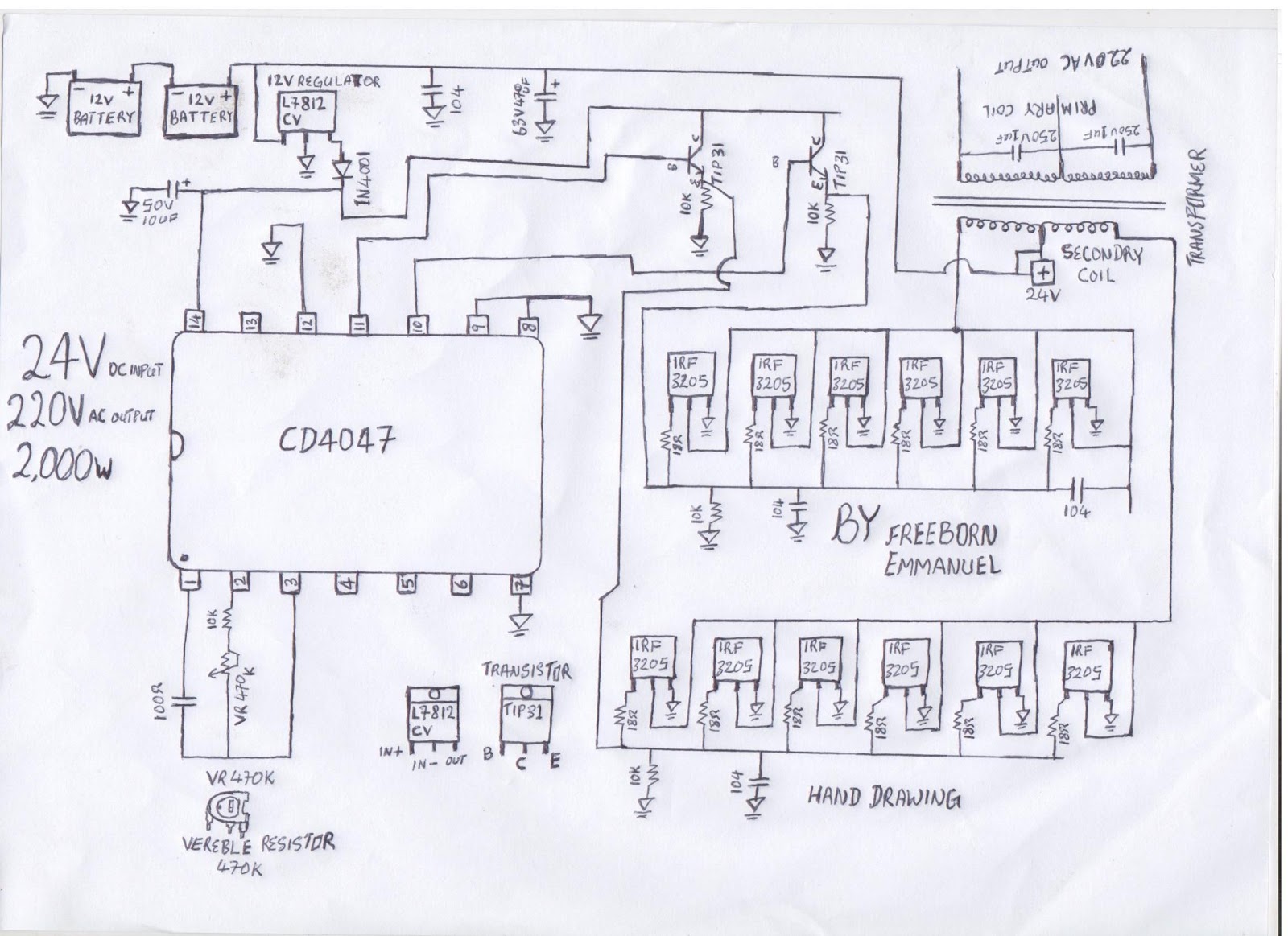
The cd 4047 ic is configured in this 12 volt to 220 volt inverter with the aid of several components like. You do not have it now. This software is used for diagram making. 1 shows single phase bridge inverter with resistive load.
In this circuitry, the 6 scrs are linked in this sequence scr1, scr6, scr2, scr4 scr3 scr5, and capacitors from c1 to c6 offer the commutation needed through scr.
Also 500w inverter circuit for you. Few days ago, gohz made a 24v 2000w power inverter in home, sharing some design schematics and circuit diagrams. 5kva ferrite core inverter circuit preparation details: Pv solar inverter circuit diagram.
You can use edrawmax for making a circuit diagram of an inverter.
It contains all the necessary features and libraries that will. In the two circuit diagram below, just use 2 transistor, 2 resistors, and one transformer only. Sine wave inverter circuit diagram with complete step by step program and coding, in this article i will discuss how to use push pull converter, sinusoidal pulse width modulation, h bridge and low pass lc filter to make pure sine wave inverter circuit diagram. If you think that this circuit is not good enough.
The major applications of inverter circuits include;
Use 24v dc supply for operation and connect 24v 5a or more than 5a transformer. R2, r3, r4, r5 = 1k, t1, t2 = irf540; We need to provide ac input power to those circuits, then only we can.