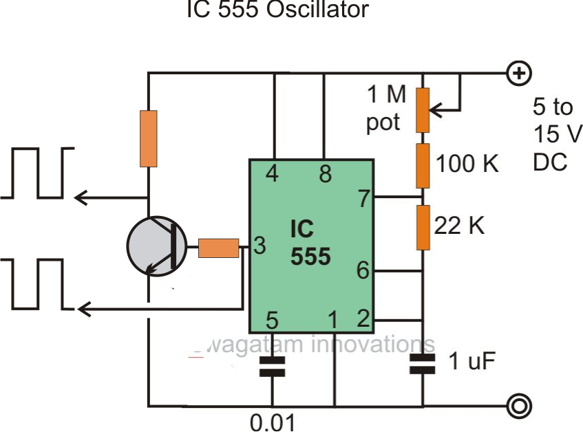
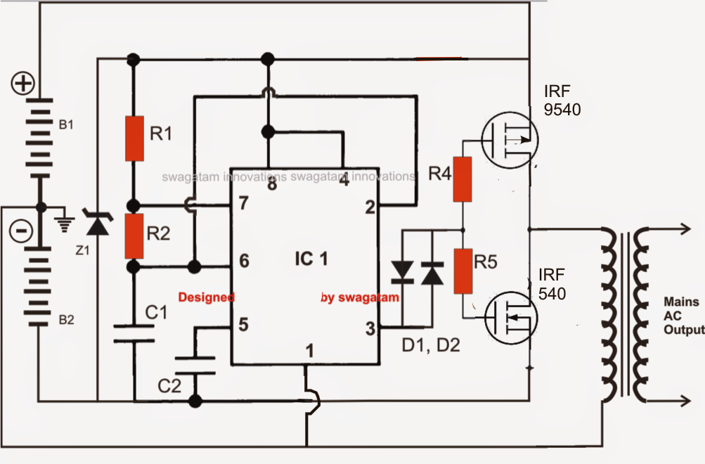
Read online simple inverter circuit using 555 presents a total of over 300 practical circuits, diagrams, and tables. Inverter circuits can either use thyristors as switching devices or transistors. We can make a very reliable inverter using ic 555 and mosfets.
Ne555 Inverter Circuit Circuit Diagram Images
Moreover the 555 timer is already a popular ic among the.
I am using 555 timer circuit for 12v to 220v ac inverter and circuit u can find in the attachment but iam not getting 220v at the secondary of filament transformer.
Ic 555 timer is an ever green integrated circuit which has tons and tons of applications; Chapter 1 outlines the basic principles and the different types of generator. You might not require more grow old to spend to go to the book inauguration as skillfully as search for them. That can be used for home powering and appliances like inverter for home.
An inverter is nothing but a dc to ac converter.
The transformer steps up the voltage to 220v ac. Use a 12v battery and battery charger circuit for this project. 20 a guide to renewable energy specifically aimed at vocational and professional construction courses a practical guide to renewable energy provides the perfect introduction to one of the construction The ic 555 can handle it like piece of cake.
Download free 230v simple inverter circuit using 555 timer my circuits 9 230v simple inverter circuit using 555 timer my circuits 9 this is likewise one of the factors by obtaining the soft documents of this 230v simple inverter circuit using 555 timer my circuits 9 by online.
As the 555 timer is one of our. Here is the simple inverter circuit diagram using 555 timer ic. All standard 555 circuits have a 1.2 to 1.4v drop from vcc, the ground side is good. In addition to these, we will use inductor, diode, capacitor, resistor and power source in our circuit.
The simple portable inverter is used for portable devices.
Sine wave inverter circuit diagram using proteus for duty cycle(d) above 50% formula: The astable multivibrator mode operation of 555 timers is utilized here for ac oscillations. 12v dc to 220v ac converter circuit using astable multivibrator. It can be easily built by any one and can be powered using a 3 volts.
There are different application where we can use portable inverter.
555 is a timer ic which is used to generate time delay. 8 rows the 555 timer ic is used as the key component which is configured as an astable multivibrator to. Our aim is to chop these 50hz square waves into the required spwm waveform using an opamp based circuit. Use as inverter circuit diagram for home.
Currently i am getting 100v ac please suggest me improvements in the circuit or some other simple circuit.
There are several ways to create an inverter when an engineer needs to convert dc to ac electricity. The timer ic555 is used as a switching pulse oscillator and it is the main part in this circuit, ic 555 configured as astable multivibrator to give continuous switching pulse, two switching transistors tip41a (npn) and tip42a (pnp) drives. Access free 230v simple inverter circuit using 555 timer my circuits 9 control solutions electronics projects vol. On these properties, it can be used to make a power inverter.
The formula for calculating this is:
Inverter is also a timing based circuit whose frequency and duty cycle are important parameter. Resistance, and capacitance using the above the time delay formula. We have seen in the last few tutorials that the 555 timer can be configured with externally connected components as multivibrators, oscillators and timers, with timing intervals ranging from a few microseconds to many hours. This is a must try inverter for beginners and first time diy inverter makers among hobbyists.
The functional diagram of a 555 timer ic consists of one npn transistor $q_{1}$ and one pnp transistor $q_{2}$.
This is a guide of inverter project for student using 555 timer ic. Any transistor circuit will have to adjust for it. Simple inverter circuit using ic 555. In the circuit above is completely circuit diagram of this project.
Chapters 2 to 9 deal with a specific type of waveform generator, including sine, square, triangular, sawtooth, and special waveform generators pulse.
The input voltage to be doubled is fed in at connector k1. The working of the pure sine wave inverter starts when the 12 volts dc is applied to the components. As a result, the circuit may require a large number of components to enhance the voltage. This circuit shows how it is possible to use a trusty old ne555 timer ic and a bit of external circuitry to create a voltage inverter and doubler.
Abhishek singh comment (0) the circuit in this article shows you a simple way to build a 12v to 230v inverter circuit diagram of 100watt power using 555 ic.
Working of pure sine wave inverter using 555 timers. These 12 volts enter the 555 timer through pin 3 of the 555 timer that is in the astable mode. And these oscillations are switched via transistor 2sc4029 to a transformer. Here is the simple inverter circuit diagram using 555 timer ic.
The following graph shows the plotting of time delay vs.
Frequency f = 1.44 / ( ( r1 + 2*r2 ) c1) duty cycle d(%) = ( r1 + r2 ) / ( r1 + 2*r2 ) for duty cycle(d) = 50% or below 50%. We can create simple small inverter circuit to handle low power devices. From the sounds of it, you may just have too low a battery voltage. A collection of 555 circuits using the 555 timer as an astable oscillator with different duty cycles.
The inverter converts simple dc voltages into ac voltages.
How 555 inverter circuit works. There are many inverter circuits using ic based oscillators around the internet, but none can beat the popularity of ic 555 which has tons and tons of applications in timing based circuits. The diagram above shows the entire design of the proposed spwm inverter circuit using ic 555, where the center ic 555 and the associated bjt/mosfet stages forms a basic square wave inverter circuit. One cycle period t = t on + t off (sec) frequency f= 1/t (hz) duty cycle d(%) = ( t on / t ) * 100.
We can achieve 220v ac at the output of just 12 volts.


