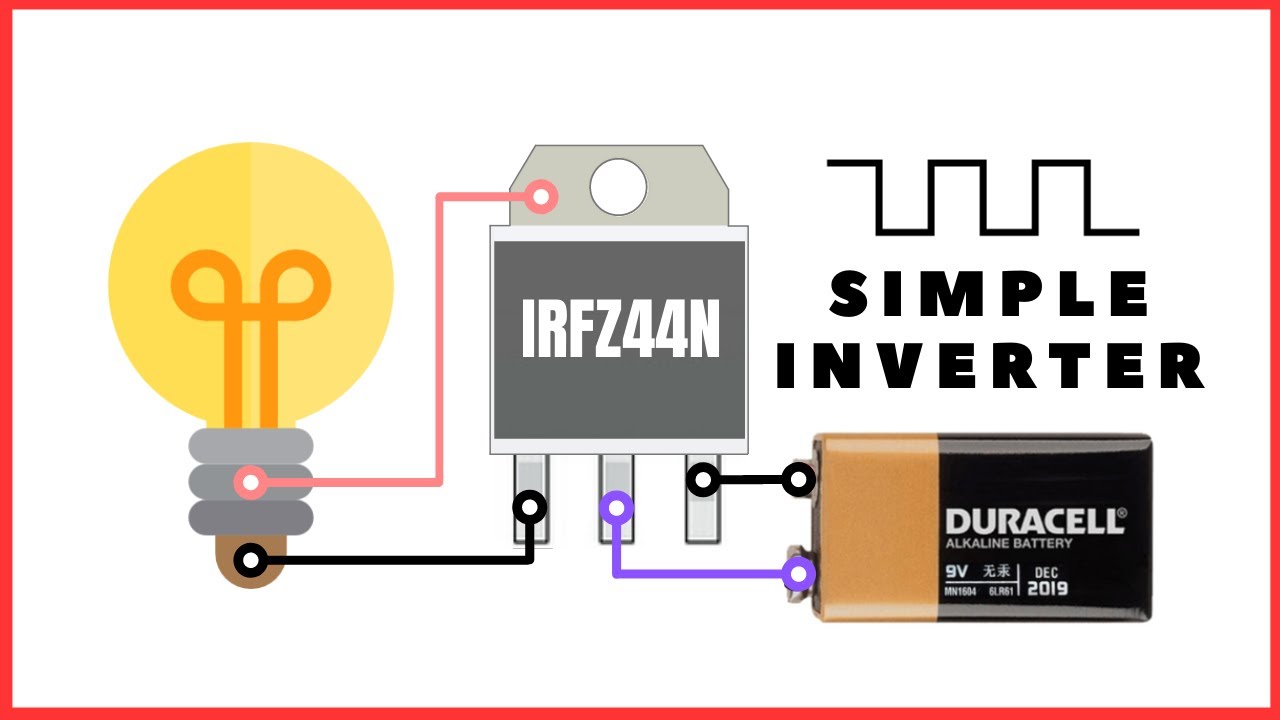
Here’s a very simple circuit inverter that converts dc current into ac current, from 12v dc to 220v ac with output power of 5w max. The circuit diagram is given below to build a simple inverter circuit using a 555 timer. Bend the 13007 transistor pins and tin the wires for better soldering.
Simple Inverter Circuit Circuit Diagram Images
Here is the circuit diagram of a simple 100 watt inverter using ic cd4047 and mosfet irf540.
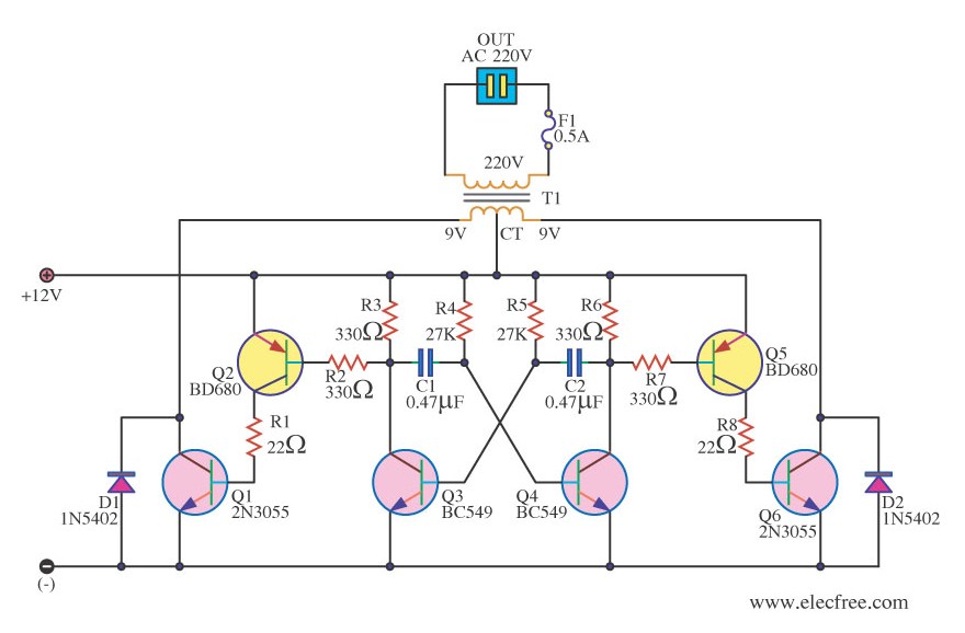
This time we used the larger power transistor 2n3055, and only two resistors are used, and the power of the resistor is selected to be larger, so the output power of the circuit will be corresponding.
This circuit used to invert low voltage to high voltage. So, in today’s tutorial, we will take a look into a step by step process on how you can build a simple 12v to 220v inverter circuit using two irfz44 mosfets. This is a simple dc to ac inverter circuit project to convert a 12v dc battery become 230v ac. The icl7660 or max1044 can be selected.
C1 = 0.01uf, c3 = 0.1uf;
Here is that the video about simple basic inverter circuit diagram from creative creator. Besides that, this circuit uses flyback transformer that can obtained from b/w or color tv or computer monitor. Op amp 1 generates a 50 hz sine wave as the reference signal. But you can use this inverter for other purposes that do not require large electric power such as mobile phone charger, small.
Op amp 2 as an inverter.
The picture above is our inverter schematic. R2, r3, r4, r5 = 1k, t1, t2 = irf540; The following diagram is the basic design diagram of inverter circuit. Arduino enthusiasts must try this inverter as this is the simplest possible inverter which can be built using a microcontroller board like arduino.
The second step is to get all symbols an inverter needs.
Here is a simple pwm dc to ac voltage inverter circuit based on ic sg 3524. Output of this astable multivibrator circuit: It is used only in lighting and power. This circuit used to invert low voltage to high voltage.
R1 = 220k pot, needs to be set for acquiring the desired frequency output.
Drag and drop all the components mentioned. Cd 4047 is a low power cmos astable/monostable multivibrator ic. Inverter circuit is typically used for emergency lighting, since the power output is small, which is about 5w only. Let’s build our simple 40 watt inverter.
How to make simple inverter circuit diagram within 5 minutes in the two circuit diagram below, just use 2 transistor, 2 resistors, and one transformer only.
220v inverter circuit using irfz44 mosfet simple 100w with fet irf540 12v to 230vac rangkaian dc ke ac panduan 500w power circuits electrical4u 555 h bridge 4 n what is an diagram 7 you can high voltage easy 150 w full 100 watts working and for newcomers watt 500. The sg3524 ic integrated circuit has all the functions necessary for the production of a regulating power. First with a double voltage module voltage for the op amp power supply. Telemetry, all aspects that require a wiring diagram, which is used to locate faults, add equipment new auxillary, etc.
You may also interested in:
Where, f is the frequency in hz. As a result, the circuit may require a large number of components to enhance the voltage. By doing simple modification you can also convert 6v dc to 230v ac or 110v ac. C is capacitance in farad.
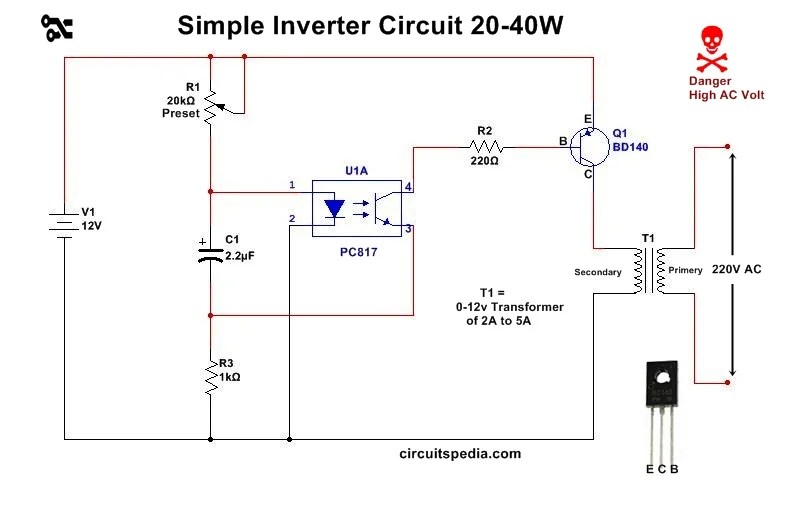
This simple low power dc to ac inverter ( dc to ac converter) circuit converts 12v dc to 230v or 110v ac.
Simple inverter circuit using arduino. => free apps => small size => monthly updates => offline and online app => compatible with any device => many category to vehicle wiring diagram # inverter circuit diagram simple inverter circuit It is uses npn transistor type 2n3055. Simplest inverter using hybrid mosfets and igbts with unipolar pwm to scientific diagram.
R1 (110 ohm/5w) and r2 (27 ohm/5w) are used to limit the current so as to reduce.
Simple inverter circuit step 1: An inverter circuit is often used in dc to ac applications and is necessary for many electronics applications. F = 1 / 1.38 x r x c. The diagram above shows the entire design of the proposed spwm inverter circuit using ic 555, where the center ic 555 and the associated bjt/mosfet stages forms a basic square wave inverter circuit.
This is a simple high voltage inverter circuit.
The 555 timer ic is used as the key component which is configured as an astable multivibrator to provide continuous switching pulses. Connect the t1, t2 transistor’s emitter together for the 12v. The above figure uses a 1w 400 ohm resistor. We can achieve 220v ac at the output of just 12 volts.
This inverter circuit functions on the principle of converting a pure dc signal into a free running square waveform, through the help of a multivibrator circuit operating in astable mode.
Simple low power inverter circuit | 12v dc to 230v or 110v ac | diagram using cd4047 and irfz44 power mosfet. Simple ic 555 inverter circuit. It is uses npn transistor type 2n3055. The circuit will convert 12v dc to 120v ac.
اینڈرائیڈ کے لیے simple inverter circuit diagram apk 1.0 ڈاؤن لوڈ کریں۔ simple inverter circuit diagram the best application for you
This simple inverter is constructed around an arduino board which gives very stable frequency of 50hz at 50% duty cycle. It can be used to power up the electronic devices which require low electrical consumption. Parts list for the above explained 150 watt inverter circuit diagram: There are several ways to create an inverter when an engineer needs to convert dc to ac electricity.
Besides that, this circuit uses flyback transformer that can obtained from b/w or color tv or computer monitor.
They can convert 12vdc from battery to 220vac or 120vac to apply small light bulbs or lamps max 10 watts. This is a simple high voltage inverter circuit. This basic inverter circuit can handle up to 1000watts supply depends the t1, t2 and transformer used. The circuit is simple low cost and can be even assembled on a veroboard.
The things required for the construction for making a whole diagram from scratch, you have to go for the software’s electrical engineering or electrical design.
R is resistance in ohm. The frequency of this astable multivibrator can be calculated by: Our aim is to chop these 50hz square waves into the required spwm waveform using an opamp based circuit.