If the cell does not exist, it is created. But to run most load like fan, tv, etc you need to have a sine wave inverter. 4) size inverter output circuit (ac) conductors according to inverter ocpd ampere rating.
5000w Inverter Circuit Diagram Pdf Home Wiring Diagram
Microtek sine wave inverter full circuit diagram.
12v dc to 220v ac inverter circuit pcb power 100w with the 555 converter diagram pdf switching transformerless basic schematic for air conditioner circuits 500w using solar working page 2 supply 3 300watt 24v simple phase voltage easy sg3525 explored build 200w model of digital report pure sine wave.
Specify the view type as schematic and click finish Sine wave inverter circuit digram with code igbt (insulated gate bipolar transistor) module is a device required for inverter use in many types of industrial equipment, and had driven the trend towards high currents and high. December 10, 2021 october 4, 2021 by debnatheletrical1. The create new view dialog box opens.
Yes no notes for inverter circuits (guide section 8 and 9):
Microtek inverter 24x 7 circuit diagram. This application note describes the design principles and the circuit operation of the 800va pure sine wave inverter. With this kind of an illustrative guidebook, you’ll have the ability to troubleshoot, prevent, and total your tasks without difficulty. A diagram shows how to properly wire a charge controller and an inverter into the same battery based pv system.
Wrg 9424 collection electrical wiring circuit diagram pictures wire.
Related book pdf book pure sine wave inverter circuit diagrams free download : Pdf design of single phase to three static power converter. Get pdf sukam inverter circuit diagram png. This is accomplished through an inverter circuit using electronic components.
500w 5000w power inverter dc 12v ac 220v circuit.
Microtek 850va and 1100 seb sine wave inverter. This inverter circuit diagram which can change the voltage 12 volt dc to 230 volt ac.scheme inverter circuit is capable of removing power output up to 3000 watt, for beginners as possible to assemble a circuit schematic this inverter will be a little complicated and confused, but if. 8/10/2017 · there’s pretty easy to make square wave inverter circuit in the internet. It has undervoltage, overvoltage, overcurrent protection, overcurrent protection is implemented by test tube drop.
Pin on 12 volt to 220 volt inverter circuit diagram.
Microtek inverter low battery, overload, mains changeover, relay drive volt, mosfet drive volt full hd diagram. A modified square wave inverter outputs a wave similar to a square wave with a delay in between cycles, while a sine wave inverter outputs a true sine wave. This document describes inverter circuits used for motor control and other applications, focusing on pwm control. Ups inverter diagrams pdf free kazmi elecom.
Most of the inverters available in the market have complicated circuit design and are not very economical.
Enter the cell name (e.g. Two types of inverters currently exist on the market; We have so many collections wire wiring diagrams and. Mr sewak mechanical 38,765 views.
In the electronics or logic design subject, the inverter is also known as the not gate, which does nothing but logical negation.elaborating more, the inverter or not gate makes the high a low and the low a high.
Demo_inverter) where you want a cell view to be created click file > new > view. Inverter circuit page 2 power supply circuits next gr. Digital inverter circuit diagram microtek. Ups inverter diagrams pdf free kazmi elecom.
Sinusoidal pulse width modulation, h bridge and low pass lc filter to make pure sine wave inverter circuit diagram.
Cd4017 100 watt inverter 12dc to 220ac voltage increase for car or other device with this supply 1 circuit diagram electronics circuit battery charger circuit. The enphase wiring diagram is here. Does total supply breakers comply with 120% busbar exception in 690.64(b)(2)(a)? Digital inverter circuit diagram microtek.
3 phase inverter circuit diagram the internet is flooded with single phase inverter circuit diagrams, but there are only few circuit diagrams of 3 phase inverter out there, a simplest possible 3 phase inverter is described here.
Introduction this report focuses on dc to ac power inverters, which aim to efficiently transform a dc power source to a high voltage ac source, similar to power that would be available at an electrical wall outlet. Inverter voltage 24v to 220v of 7 kw air conditioning yoreparo circuit diagram electrical circuit diagram electronics projects. Home ups inverter circuit diagram pdf. 4 simple uninterruptible power supply ups circuits explored homemade circuit projects.
Microtek inverter circuit diagram pdf.
We will show two basic ups inverter with batteries connection the home distribution board. Ups inverter wiring diagram with auto manual changeover switch system. Diagram for everything inverter circuit 1000w pdf. 1 the junction box at the pv array wiring from pv array to the disconnect switch on the house the disconnect switch the wiring from the disconnect switch to the circuit breaker panel.
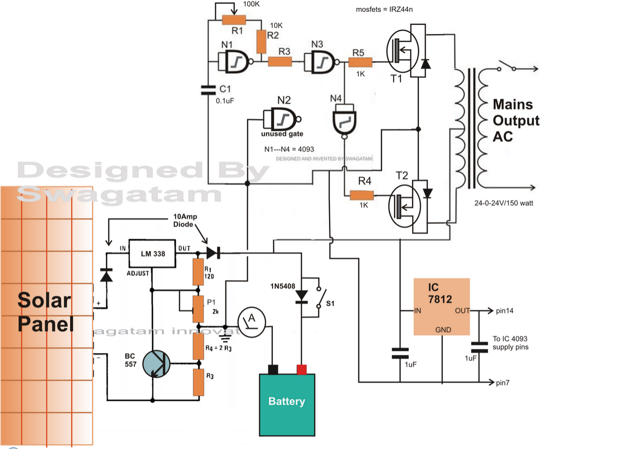
Here is the circuit section, get understanding the basics of this power inverter, diy an inverter now.
3000w power inverter 12v to 230v circuit and products. Service manual 1500w inverter full schematics and pcb rar power schematic diagram preview. Three phase inverters require microcontroller design where the timings of the all three phases need to be precisely. Before jumping into the inverter circuit diagram, it is necessary to know the logical symbol of the power inverter.


