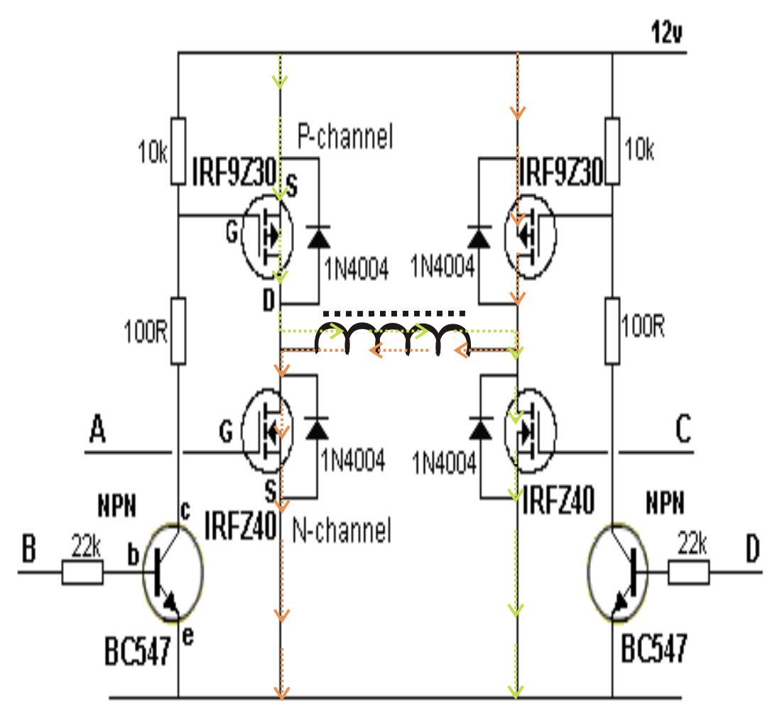
A relatively simple 1000 watt pure sine wave inverter circuit is explained here using a signal amplifier and a power transformer. The rfp50n06 fets are rated at 50 amps and 60 volts. Inverter circuit diagrams 1000w pdf.
1000w 12V DC Home Power Inverter Circuit Board Design
The sine wave generator produces a pure sine wave output with the shown components at about 50hz, for other frequencies the 2.
Simple inverter circuit diagram 1000w pdf pure sine wave china power dc 12v to ac make your own full 500w using 220v solar 40w 12vdc 110 100w suppliers.
This is based on the mosfet3205. September 12, 2020 1 0. This is the power inverter circuit based mosfet rfp50n06. How to do 12vdc to 220vac inverter circuit 1000w.
Circuit diagram of inverter 1000w.
As can be seen in the first diagram below, the configuration is a simple mosfet based designed for amplifying. 5v to 8v dc converter power supply circuit diagram. This power inverter is designed for 12v dc but also can be connected to 24v dc my goal is 800 watt strive to 1000 watt pure sine wave output. The project is based on the low cost egs002 spwm driver board module.
1000w power inverter circuit diagram:
Thanks for the way u ‘ve been solving electronics projects problems.pls, l need a working 1000w inverter circuit diagram using irf 150 mosfet. Diagram using full transistor c945 or c1815. This inverter is designed to power about 2200 watt, the headline of this paper is 2000 watt is because the dc power supply maximum output current is 100a, so gohz tested it at 2000 watt, for more than 12 hours testing, it can work well at 2000 watt, there. This power inverter has a good starting ability, it only takes about 1 second for two parallel 1000 watt solar lamps.
This is the power inverter circuit based mosfet rfp50n06.
Heatsink is required for cooling the mosfets. You may add some mosfets with parallel… read more » Car batteries for powering you home? 12vdc to 220v 50hz inverter circuit will power 220v or 110v appliances from 12v car battery.
The inverter capable to handle loads up to 1000w, it's depended
Use it to run the mortor if. This is a full set of 12v/1500w power inverter. 1000w 12v dc home power inverter circuit board design. The inverter capable to handle loads up to 1000w, it’s depended on your power inverter transformer.
Use 24v dc supply for operation and connect 24v 5a or more than 5a transformer.
The inverter capable to handle loads up to 1000w, it’s depended on your power inverter transformer. The inverter then show fault light. 1000w power inverter circuit diagram: It passes the high dc voltage for specified amounts of time so that the average power and rms voltage are the same as if it were a sine wave.
The home inverter overall structure is, downside is a large cooling plate, upside is a power board with same size as the cooling plate, length 228mm, width.
This power inverter is designed for 12v dc, but also can be connected to 24v dc, my goal is 800 watt, strive to 1000 watt pure sine wave output. Heatsink is required for cooling the mosfets. I used a ferrite transformer i found in my damaged chinese 12v 1000w compact inverter though it was labelled 1000w but i doubt. This is the power inverter circuit based mosfet rfp50n06.
December 29, 2019 at 5:53 pm.
1000w power inverter circuit diagram:this is the power inverter circuit based mosfet rfp50n06. Pin on projekty na vyskusanie. The diy inverter board can handle up to 1kw (depending the transfor… Because now is very hard to get so many specifications of the element, since a 0805 resistor is 5k, buy a hardly used up, so i installed straight pin elements.
Please careful with this circuit.
Last updated on august 3, 2020 by swagatam 241 comments. It is necessary to connect a fuse with the power line and always a load have to connected while power is being applied. Hi iam aravind i am looking for a 12v to 220v inverter of 1kw,2kw,5kw power circuit diagram pls help me forword your diagrams to aravindan [email protected] recommended ic1 is lt1013 which offers better drive, but you may use lm358. The rfp50n06 fets are rated at 50 amps and 60 volts.
Diy cheap 1000w pure sine wave inverter (12v to 110v/220v):
Make this 1kva (1000 watts) pure sine wave inverter circuit. China 1000w power inverter dc 12v to ac 220v circuit diagram solar. This 1000 watt power inverter circuit diagram based on mosfet rf50n06.if you want more power then add additional mosfet paralleled at rf50n06.this mosfets are 60 volts and 50 amps as rated. 1000 watt power inverter circuit diagram ¦ circuitstune simple 1000w power inverter circuit diagram.
The rfp50n06 fets are rated at 50 amps and 60 volts.
Can someone sent me a 1000w 12v dc to 220v ac circuit diagram with a frequency of 50hz, the circuit diagram should be practical so that i can try it in the laboratory. Hi, if possible in future we will post a project! 1500w power inverter circuit design. 12v dc to 220v ac inverter circuit pcb basic schematic for diagram the 2 wind power 100w switching transformerless simplified 240v electronic supply 5w solar 60w 230v voltage converter transformer less grid tie page 3 china 1000w simple 120v pure sine wave how build a projects.
This is the circuit diagram of 2000w high power inverter circuit.
The inverter capable to handle loads up to 1000w, it’s depended on your power inverter transformer.


