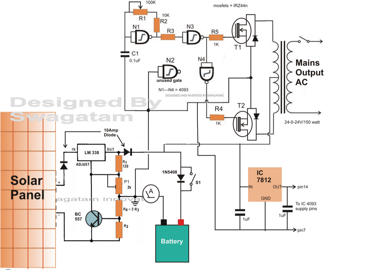
And although there are different types of the solar inverters, but they all have the main components, let us see what are they and what are their functions as following: How to identify the inverter circuit board electronic components. Electrical specifications of an inverter.
12V DC to 220V AC Inverter Circuit
An inverter which uses minimum number of components for converting a 12 v dc to 230 v ac is called a simple inverter.
With q1,q2=2n3055 and t1= 15 a, the inverter can supply about 300 watts.
Bipolar junction transistors (bjts) bjt or a bipolar junction transistor is a three layered device which is capable of controlling the current flow. Inverters are devices that convert dc input supply to ac (alternating current). Today we will detail the introduction to 74hc04 to you. The inverter internally is made up of switches, a transformer, a battery, a mosfet, and an amplifier.
Major components of inverters major components of an inverter.
The dc which is stored in the battery is altered to the ac. They are also called power inverters. Inductors and capacitors are used to filter the output. The main working of microcontroller is to control the switching of signals according to the requirements.
Hello everyone, this is rose.
Major components of an inverter. The inverter is considered as the brain of the solar system. Resistance in the circuit boards with the letter “r” said, the unit has: Aluminum heat sink= cut as per the required size;
The main component of the solar inverter is the output stage;
Simple modified sine wave inverter circuit. Square wave inverters are now confined to underdeveloped countries only. The 74hc04 is a hex inverter. Ohm (ω), qian ω (k), megohm ω (m) resistance symbol means:
Circuit of series inverter :
An inverter design and components vary with requirements but following components are most commonly used in designing an inverter. Power inverters have numerous applications in power electronics field. A 12 v lead acid battery is the most standard form of battery which is used for operating such inverters. Working of 12v to 230v inverter circuit diagram using 555 ic:
Car batteries for powering you home?
The circuit board of inverter mainly includes power board, control board, drive board and panel. Automobile battery= 12 volts/ 10ah. Igbt is a kind of power device, which assumes the function of power conversion and energy transmission in the power inverter. How to build a power inverter circuit needed components.
There are usually a few other components within the ups module such an ac distribution module with an input circuit breaker, boost tap transformer, control and monitoring subsystems.
Simple inverter circuit using arduino. At the same time, igbt is also one of the most unreliable components in the power inverter. Simple 3 phase inverter circuit. The diy inverter board can handle up to 1kw (depending the transfor…
Let's begin with the most simplest in the list which utilizes a couple of 2n3055 transistors and some resistors.
R1, r3, r4 1kω(1/4watt) r2 4.7kω(1/4watt) 12v power supply circuit; The switches play an essential role in this. Simple inverter using ic 555. Diy cheap 1000w pure sine wave inverter (12v to 110v/220v):
It is the heart of the inverter.
The type of battery we will use for this circuit is one of those big 12v batteries, such one you would find in a car. Inverters of the past were inefficient and unreliable while today’s generation of inverters are very efficient (85 to 94%) and reliable. T1, t2 = 2n3055 power transistors. It is used in various applications like induction heating, ups, controlling electric motors, refrigerators, solar and.
The proposed inverter is very simple, it consists of just three stages, we have simplified the inverter stages further by eliminating the boost converter stage which is a bit complex for a homemade transformerless inverter.
The cd 4047 ic is configured in this 12 volt to 220 volt inverter with the aid of several components like. The project is based on the low cost egs002 spwm driver board module. The electronic devices connected to the output are secured by the mov (metal oxide varistor). The ups module contains an inverter which is an electronic device that changes direct current (dc) to alternating current (ac).
We'll show in detail how to build this circuit below.
Dc power source / battery bank. Microcontroller is the main and integral part of an inverter. Power transformer 120vac primary 12vac secondary; The basic circuit of a series inverter is shown below.


