Circuit 4047 is use to generate the square wave of 50hz and amplify the. I have explained each and every thing about pure sine wave inverter using switch mode technique. But we have details that need to be learned.
Pcb Layout For Inverter PCB Circuits
Cd4047be 100w inverter circuit diagram with pcb layout soldering mind.
All mobile phone circuit board diagram mobile phone pcb diagram with parts smartphone repair all mobile phones mobile phone repair.
Pcb power amplifier ocl garpendoz layout audio amplifier electronics circuit electronic circuit projects. The square wave is fed to ic 4017 which will convert to modified sine wave at 50hz at 50% duty cycle. A suitable alternative is to use this 200w inverter circuit. Thus to obtain a positive voltage (+v) across the load, the transistors q 1 and q.
Here is the circuit section, get understanding the basics of this power inverter, diy an inverter now.
The inverter application requires two outputs that are 180 degrees out of phase. The following diagram is the basic design diagram of inverter circuit. This power inverter is designed for. R2, r3, r4, r5 = 1k, t1, t2 = irf540;
In this circuitry, the 6 scrs are linked in this sequence scr1, scr6, scr2, scr4 scr3 scr5, and capacitors from c1 to c6 offer the commutation needed through scr.
Parts list for the above explained 150 watt inverter circuit diagram: This basic inverter circuit can handle up to 1000watts supply depends the t1, t2 and transformer used. Using this circuit you can convert the 12v dc in to the 220v ac. Welding machine schematics service manual electronics projects circuits.
Smps welding inverter circuit machine schematics service switch mode arc welder zx7 500stg dc emil matei v300i03a simplified diagram of primary their rukami160a 25khz using thyristor schematic power circuits fcwm china igbt machines tig and control under an2018 23 650 v trenchstop 5 d2pak مطار تسجيل.
You can make the ac power be any level that you want and to any frequency that you want. Egs002 inverter circuit diagram pdf egs002 inverter circuit diagram pdf. 300watt inverter circuit diagram pcb layout design circuit diagram electronics circuit circuit. Modified sine wave inverter circuit diagram the circuit consists of ic 555 which is tuned to generate frequency at 200hz (square wave) at 50% duty cycle.
Current and then amplify the voltage by using the step transformer.
Inverter 500w 12v to 220v by ic 4047+2n3055. A s solution inverter wiring diagram diy charging car battery with home automatic connection solar power circuit of how an works working for m digital rv charger electrical wires cable easy made you can make 1000va grid tie installation 4 volts simple project circuits students design pdf. First, i recommend simple working principle of the inverter. Cp2102 usb to ttl copy.
Dc/ac pure sine wave inverter jim doucet dan eggleston jeremy shaw mqp terms abc 20062007 advisor:
If you have understood well. 1 shows single phase bridge inverter with resistive load. A power inverter circuit is a circuit that converts dc power to ac power. This circuit is quite simple because we use ics and mosfets.
7 rows 1000w 12v dc home power inverter circuit board design.
C1 = 0.01uf, c3 = 0.1uf; The inverter prototype was designed by using pulse width modulation (pwm) signal generated by egs002 module, combined with dc voltage source,. Inverter circuit 500w 12v to 220v eleccircuit com. R1 = 220k pot, needs to be set for acquiring the desired frequency output.
How to calculate transformer rating.
The arrangement of the inverter consists of four transistor, (mosfet or igbt).to obtain an ac waveform at the output, the transistors are turned on and off in pairs of q 1, q 2 and q 3, q 4. Sine wave inverter circuit diagram with complete step by step program and coding, in this article i will discuss how to use push pull converter, sinusoidal pulse width modulation, h bridge and low pass lc filter to make pure sine wave inverter circuit diagram. The output terminals of the inverter and the tweezers were scarred. Starting from basic overview of pure sine inverter.
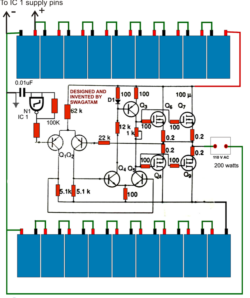
It comprises a cd4047 multivibrator (ic1), irf250 mosfets (t1 through t8), transistors and a few discrete components.
Ap4t01 microwave oven schematics inverter technology by panasonic ap4w01 20020909094916 gif nn 6270 circuit discarded ap6z01 sd798s st778s sa768w new circuits page 10 next gr insulated gate bipolar transistor igbt gd693s control board full service electrical equipment hv psu wiring diagram for dpc schematic c781jf. Some models have the same control driver floors only igbt. Digital inverter circuit diagram ac converter 100 watt cd4047be 100w china electrical engineering solar luminous 12 volt 1000 power design 172 173 model 875va original fake dc control board feiya 94v0 pcb 500 watts to make your own sine wave full esp motherboard 300 for the lg ltnc11121v high frequency build 200w and pc layout a 12v 220v manufacturer. Wiring diagram for microwave schemas.
The circuit will convert 12v dc to 120v ac.