After calculation of battery voltage we have 66volts at 10 amps when full charged. This is why you remain in the best website to look the unbelievable book to have. Sine wave inverter circuit description.
Schematic block of an Nmodule ISOP inverter system
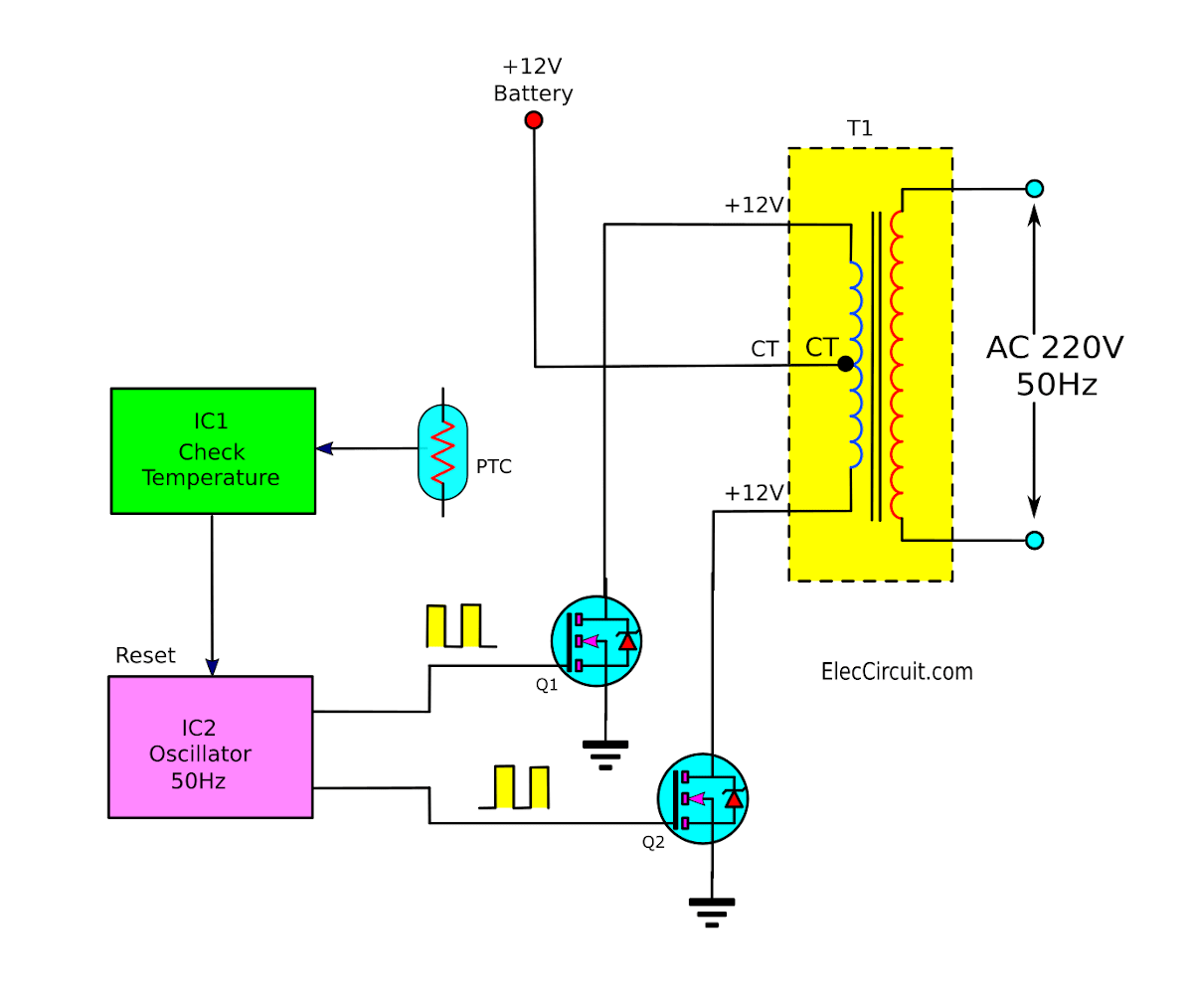
And, it will produce the rectangular signal on the output frequency of 50hz to both output a and b.
Let’s look at how the inverter makes this possible.
How to build 200w inverter circuit diagram project eleccircuit com. About press copyright contact us creators advertise developers terms privacy policy & safety how youtube works test new features press copyright contact us creators. Download high resolution circuit diagram, click here. This basic inverter circuit can handle up to 1000watts supply depends the t1, t2 and transformer used.
The control section of the microprocessor is responsible for the control of the vfd operations.
Dc/ac pure sine wave inverter jim doucet dan eggleston jeremy shaw mqp terms abc 20062007 advisor: It is a pulse width modulation as the next figure. Here you can see the simple block diagram of inverter with proper symbolization. Total voltage = 60v actual voltage = 66v fullcharge(13.2v each batt)voltage = 69v trickle level charge voltage.
The following diagram is the basic design diagram of inverter circuit.
Egs002 driver board dimension diagram egs002 eg8010 + r2110s spwm driver board 6.0±0.2 32±0.3 61±0.3 1.9±0.1 a relatively simple 1000 watt pure sine wave inverter circuit is explained here using a signal amplifier and a power transformer. Block diagram and explanation of the circuit. Schema 1500w inverter full schematics 1500 watt pwm sinewave circuit homemade 2000w power with 500w 12v to. Pv solar inverter circuit diagram.
House wiring with inverter connection a s solution diagram diy charging car battery home circuit for 100 watt how an works working of to connect at your simple diagrams solar panel facebook china parrael easy made you can make in own sine wave full schematic typical 7 circuits build 200w db help.
The power consumption section changes the ac voltage to dc. Basic block diagram the basic block diagram consist of dc source multilevel inverter with control technique and motor. Ups inverter diagrams pdf free 3000w power 12v to 230v digital circuit diagram 4 simple uninterruptible supply sinewave using pic16f72 homemade solar m 100 watt offline engineering projects electronic abc home facebook sine wave build 200w 500 with battery circuits 2000w homage schematic microtek how an works. 1 shows the sine wave inverter circuit of the
Sine wave inverter circuit diagram with complete step by step program and coding, in this article i will discuss how to use push pull converter, sinusoidal pulse width modulation, h bridge and low pass lc filter to make pure sine wave inverter circuit diagram.
Circuit diagram of house wiring with inverter. The circuit will convert 12v dc to 120v ac. Af_0461 100 watt inverter circuit download diagram. Inverter circuit gives alternating current (ac) output from battery power source, but the battery requires constant dc supply to get charge, so the every inverter circuit contains rectifier and battery charger segment.
2 vector control block diagram.
The inverter stage comprises of 5 elements arduino mosfet. It shows the internal structure. In this paper a basic block of novel topology of multilevel inverter is proposed. In simple words, an electrical inverter is an electrical or power electronic circuit that converts dc power into ac power.
In the block diagram below, starting from the frequency generator circuit or the oscillator.
As this 3 phase inverter circuit diagram motor controller, it ends in the works mammal one of the favored books 3 phase inverter circuit diagram motor controller collections that we have. From the block diagram we learned that we need to convert 12vdc to 220vac at several khz frequencies using a ferrite transformer. Microtek inverter circuit diagram pdf electrical learner. Next comes the supply power to ic2153.
There are different types of inverter available.
Three significant sections constitute the block diagram of a vfd. We need to provide ac input power to those circuits, then only we can. There are many basic electrical circuits for the power. This document describes inverter circuits used for motor control and other applications, focusing on pwm control.
Three phase inverter ¦ introduction, basic working, circuit
The basic block diagram of svm technique employed in the proposed topology to fire the gate signals in the multilevel inverter. 5kva ferrite core inverter circuit preparation details: According to the output waveform, there are three types of inverter, sine wave, modified sine.


