The symbol for a battery is shown below. Later when you come across symbols you don’t know, you can come back here to identify what it is. It is a small chip made up of semiconductor material upon which multiple micro electrical components are fabricated to perform specific task and reduce size.
How to Read and Interpret Electrical Shop Drawings Part
Two defined level which is 0’s and 1’s (in other words, low and high or on and off respectively).
American standard code for information interchange (ascii) b.
An integrated circuit (also referred to as an ic, a chip, or a microchip) is a set of electronic circuits on one small plate (chip) of semiconductor material, normally silicon. An electronic symbol is a pictogram used to represent various electrical and electronic devices or functions, such as wires, batteries, resistors, and transistors, in a schematic diagram of an electrical or electronic circuit.these symbols are largely standardized internationally today, but may vary from country to country, or engineering discipline, based on traditional conventions. Inputs and outputs of logic gates are in two levels termed as high and low, or true and false, or on. Remember me on this computer.
Ic (integrated circuit) it is a symbol of generic ic (integrated circuit).
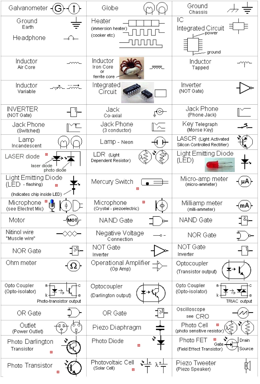
The standard circuit symbols are important for circuit schematic diagrams. A schematic showing the symmetrical complementary output stage of an amplifier is easier to read with mirrored transistor symbols. A logic gate is assigned as an elementary building block of digital circuits. Below is an overview of the most used symbols in circuit diagrams.
How to disable firefox's session restore crash recovery feature
How to identify computer chips or integrated circuits on circuit boards; Ics can be made very compact, having up to several billion transistors and other electronic components in an. Ieee standard american national standard canadian standard graphic symbols for electrical and electronics diagrams. The index lists components by general classification.
These factors will help designers create a direct and functional design to produce the desired electrical behavior.
Use edrawmax for circuit diagram creation using the correct circuit symbols in the correct places and needs is important because using the wrong symbol takes your production down. Every integrated circuit symbol can configure with the data of sections, number of inputs and outputs, number of top pins and base pins. How to build an oscillator circuit; Because the electronics industry has not adopted a single symbology standard, cie has included the most frequently used symbols that represent each component.
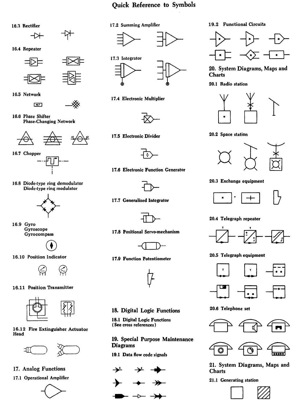
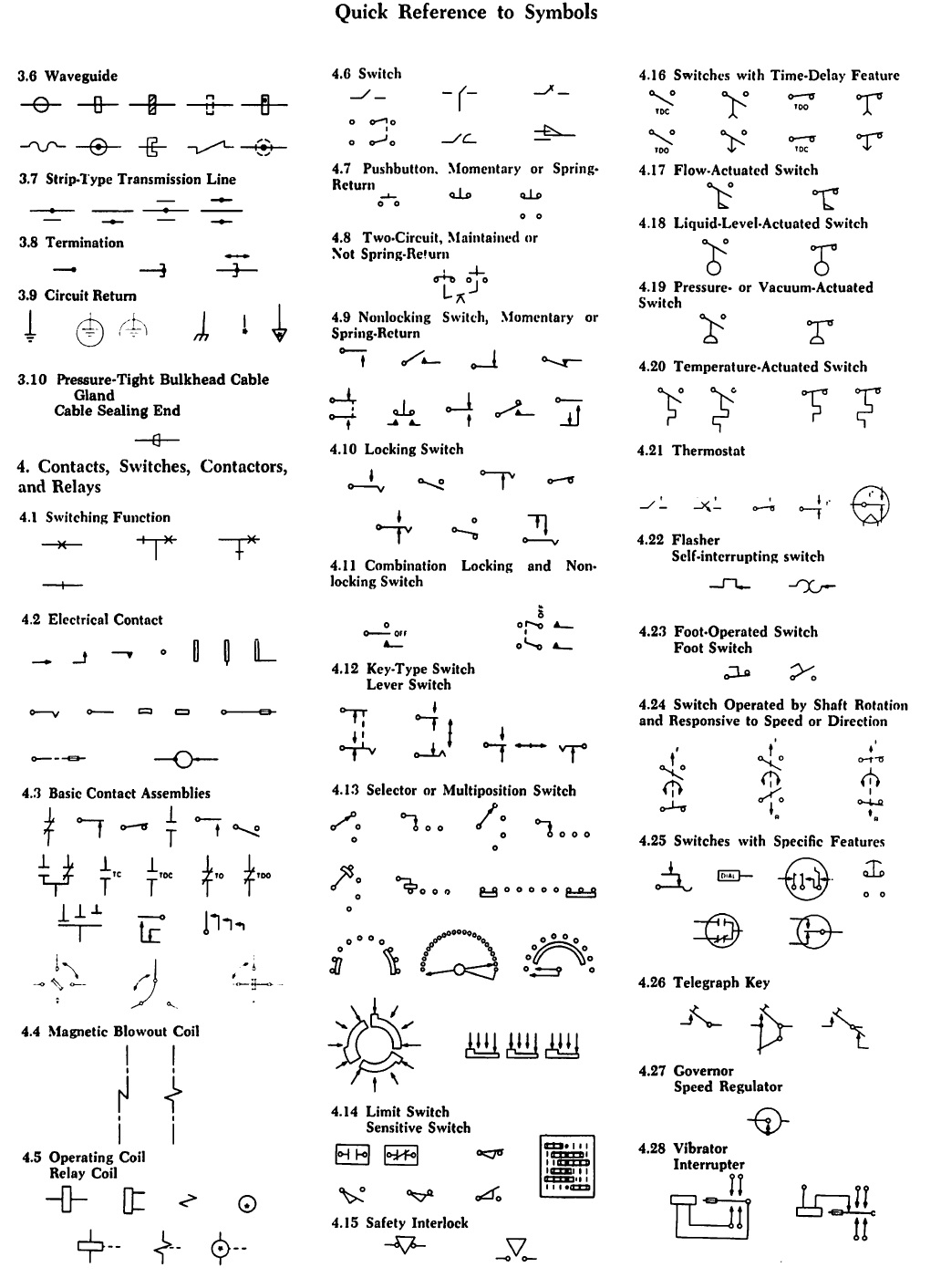
The american national standard graphic symbols for electrical and electronics diagrams (including reference designation letters).
Number, or symbol on the keyboard is represented as a binary number in computer memory. An integrated circuit or monolithic integrated circuit (also referred to as an ic, a chip, or a microchip) is a set of electronic circuits on one small flat piece (or chip) of semiconductor material, usually silicon. These types of ics work on the basic digital system i.e. Enter the email address you signed up with and we'll email you a reset link.
Pin naming, pin setting, and pin arrangement are the 3 most important factors to consider in creating a good symbol for your ic devices, being the primary element in schematic drawings.
Integrated circuits can be defined as: This can be made much smaller than a discrete circuit made from independent electronic components. Standard circuit component symbols for integrated circuit drawings. The american standard is of course far simpler and easier to remember.
In general, the ansi standard is still common in the united states.
This is an australian standard for electronic component symbols. This can be made much smaller than a discrete circuit made from independent electronic components. The database includes around 1750 circuit symbols overall. The symbols listed in this handbook were collected after much research by the technical staff of cleveland institute of electronics, inc.
Logic gate is considered as a device which has the ability to produce one output level with the combinations of input levels.
An integrated circuit (also referred to as an ic, a chip, or a microchip) is a set of electronic circuits on one small plate (chip) of semiconductor material, normally silicon. This ieee standard for circuit symbols has various release dates. Standard for use of the international system of units (si): Nowadays, the iec 60617 standard is the international standard for these electronic symbols.
Schematic symbols for integrated circuits.
Log in with facebook log in with google. Some examples of standards which describe resistor symbols: This standard for electronic component symbols is the american one and is also known as ieee std 315. Microprocessor and micro controller is the example of digital ics which contains of million of flip flops and logic gates.