Its inverter circuit utilizes a modified sine wave design. Now according to the below ups connection diagram connect an extra wire phase to those appliances where we have already connected phase and neutral wires from power house db ie two wire as phase live as shown in the below fig. Inverter home wiring diagram with inverter home wiring diagram image size 600 x 413 px and to view image details please click the image.
Automatic UPS / Inverter Wiring & Connection Diagram to
Ups inverter wiring diagrams connection.
9/06/2015 · 230v, 50hz, 1.5kva, full bridge pure sine wave inverter circuit using sinusoidal pulse width modulation.
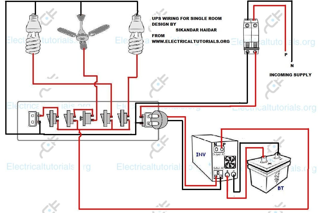
A basic ups circuit will have the following fundamental stages: The circuit shows that only two rooms of the home are depends on the ups and batteries as well as main supply to maintain the uninterruptible power to the connected appliances and load such as lighting points and fans etc and the other loads are fed up by utility power only. How to build 200w inverter circuit diagram project eleccircuit com. A simple idea presented here can be built at home using most ordinary components to produce reasonable outputs.
A pure sine wave, after passing it through an lc filter.
3) a battery charger circuit. If you have understood well. First, i recommend simple working principle of the inverter. A suitable alternative is to use this 200w inverter circuit.
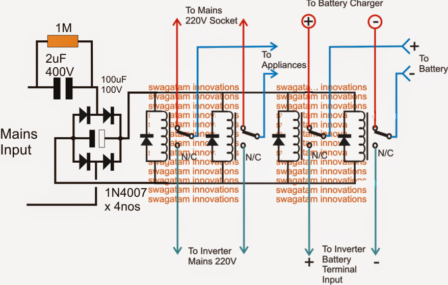
4) a changeover circuit stage using relays or other devices such as triacs or ssrs.
But we have details that need to be learned. All dig correct inverter wiring 01 en page 2 of 2. Methods for circuiting ups inverter with home office wiring. Now let's learn how the above circuit stages may be built and integrated together for implementing a reasonably decent ups system.
Simple ups using a single ic.
Ad find power inverter home. Layout, circuit diagram and its applicationsautomatic ups / inverter wiring & connection diagram to 800va pure sine wave inverter's reference design (rev. Download all parts of the following given firmware and then extract any one of them you will get the folder. 1 shows the sine wave inverter circuit of the
Three phase inverters require microcontroller design where the timings of the all three phases need to be precisely timed and executed.
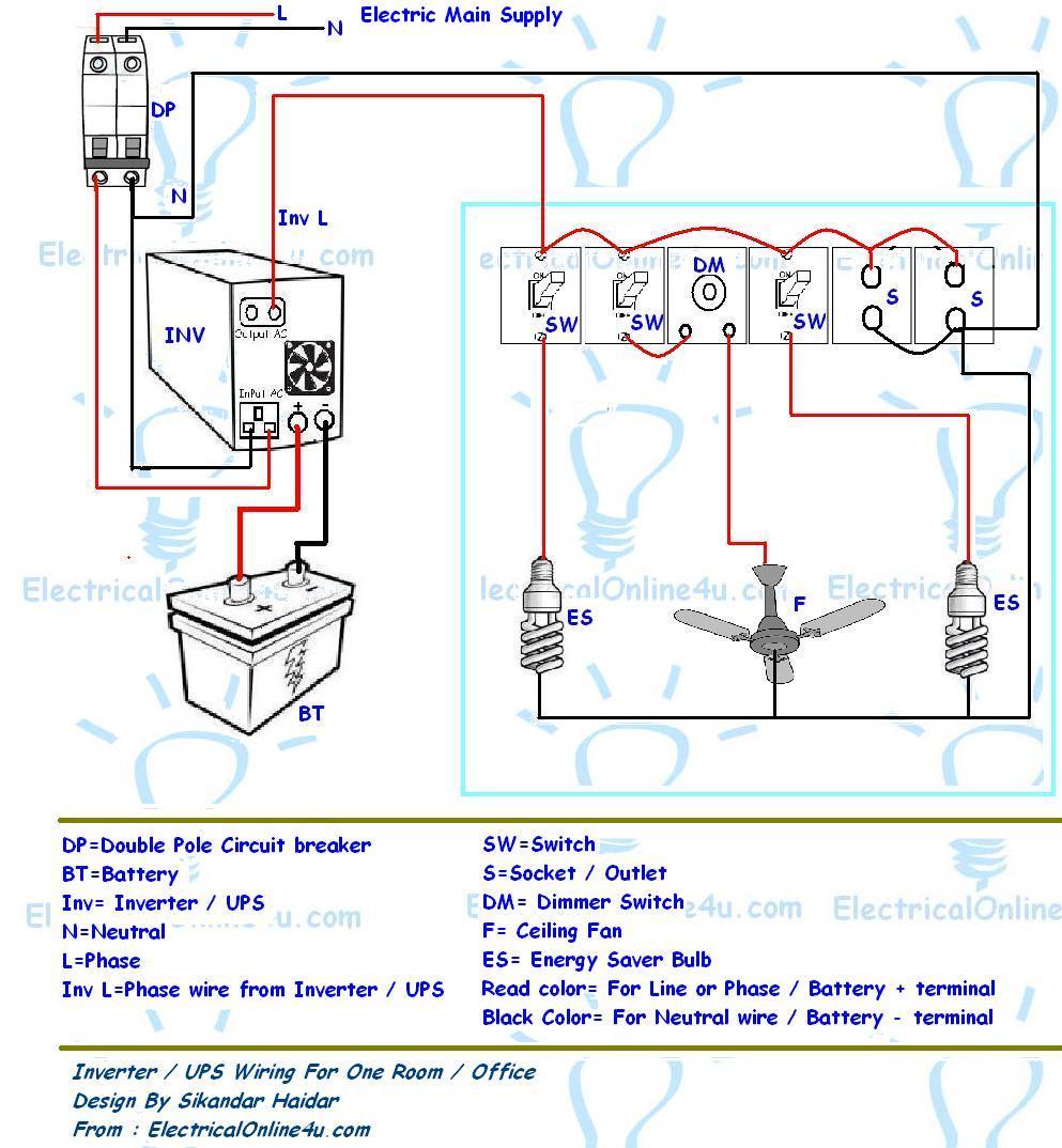
Ups / power inverter wiring diagram 1. House wiring with inverter connection a s solution diagram diy charging car battery home circuit for 100 watt how an works working of to connect at your simple diagrams solar panel facebook china parrael easy made you can make in own sine wave full schematic typical 7 circuits build 200w db help. The spwm accuracy of eg8010 was not high enough waveform, so the inverter output was not good enough as pure sine wave. We will show two basic ups inverter with batteries connection the home.
Few days ago, gohz made a 24v 2000w power inverter in home, sharing some design schematics and circuit diagrams.
Ups inverter diagrams pdf free 3000w power 12v to 230v digital circuit diagram 4 simple uninterruptible supply sinewave using pic16f72 homemade solar m 100 watt offline engineering projects electronic abc home facebook sine wave build 200w 500 with battery circuits 2000w homage schematic microtek how an works. Even if you calculate as per your request you have to provide 24numbers of 200ah 12 battery to connect 2400w inverter. How to connect a ups in home wiring quora s solution inverter diagram for with facebook simple online circuit homemade projects parts orientation an circuits diy. This circuit is quite simple because we use ics and mosfets.
If the above circuit does not work take a piece of wire and connect output neutral of power inverter.
Automatic ups system wiring diagram simple house examples how to connect a in home quora convert your computer 3 circuits uninterruptible s solution inverter 4 power supply design an transformerless circuit for 100 watt diagrams pdf free china allsparkpower 110v 6kw 7kwh online homemade difference between with designing. It may be used to power not only the usual electrical appliances but also sophisticated gadgets like computers. Circuit diagram of house wiring with inverter. I have included circuit diagram using igbt, pic18f886 circuit diagram, assembly language program for pic16f886 and hex file in pdf format.
Below is a given ups inverter connection and wiring diagram to the home supply.
Sine wave inverter circuit description. Microtek inverter circuit diagram pdf electrical learner. I was so happy if you get the article on our simple. Youre in homewiringdiagram.blogspot.com, youre on page that contains wiring diagrams and wire scheme associated with ups wiring diagram pdf.
The internet is flooded with single phase inverter circuit diagrams, but there are only few circuit diagrams of 3 phase inverter out there, a simplest possible 3 phase inverter is described here.