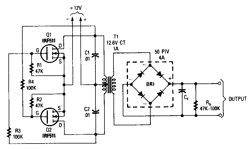
This circuit is literally a voltage inverter, i.e. The input voltage to be doubled is fed in at connector k1. The maximum current output of the circuit is about 280ma, more than enough for a few op amps.
Cheap High Voltage Low Current DC to DC Inverter
In many circuits, we need to generate an internal adjustable voltage.
The main circuit includes an inverter dc power supply, high frequency high voltage transformers, igbt bridge inverter, protection circuits, high frequency high voltage silicon stack (rectifier) , etc.
For better regulation, a 79lo xx series regulator can be used. Usually, the inverter is an electronic device, but sometimes it can be made with mechanical components. This circuit shows how it is possible to use a trusty old ne555 timer ic and a bit of external circuitry to create a voltage inverter and doubler. Common types of inverters produce square waves or quasi.
However, current source type inverters are still in use for some applications.
Position sensing of the motor shaft (resolver replacement). T1 can be an eht (extra high tension) transformer used in television sets. Tip3055 must be mounted on a heat sink. For an eht from 20inch tv, the output voltage will be 8 to 10 kv @12v supply voltage.
Many fields use this inverter, such as motor control, ups, and solar inverter systems.
Furthermore, voltage source type inverters, which do not need a reactor on the dc side, can be made more compact than current source type inverters. The main function of the inverter is to convert the dc power to ac power by using the power electronics like the igbt and mosfet. An inverter may produce a square wave, modified sine wave, pulsed sine wave, pulse width modulated wave (pwm) or sine wave depending on circuit design. The efficiency of the power inverter is more than 95%.
The high frequency power inverter includes two parts, main circuit and control circuit.
Starting from a 30 volt power supply this high voltage converter circuit can deliver a voltage between 0 to 3 kv (version 1) or from 0 to 10 kv (version 2). A zener diode may also be used to regualte the output voltage. Safely and efficiently control and protect the power switch (igbt/sic). There are many types of gate signals that can be imple mented.
Such setups can be witnessed in power rooms of office buildings, industries, school / college etc.
Inverters need a gate driver circuit to drive the power electronics switches used in the circuit for the conversion. The control circuit includes a current, voltage sampling and processing unit, driver circuit, pwm. V+ can be anywhere from 4 to 16v. This circuit is not an efficient one and is not suitable for any serious applications.
An inverter of the kind you mention (which produces ac from dc) is way more complex and expensive, and a different circuit altogether.
The circuit shown here only deals with dc, does not mess at all with ac. The power inverters are also used in controlling speed and torque in electronic motors. With an output voltage of 170 volts, the output of the comparator should have a 50% duty cycle and automatically adjust to a less than 50% duty cycle if 37. N3 are connected as astable multivibrator that commands the darlington t1/t2 with an rectangular impulse of 20 khz.
A 12v lead acid battery can be used for powering the circuit.
It 'flips' some voltage above ground to some voltage below zero. The following report discusses the design and implementation of a gate driver circuit for a three phase inverter using 180 degree conduction.


