In the case of low impedance load, series reactors are needed for each phase. 15 high voltage circuit diagramvalue of vs as shown. Op amp 1 generates a 50 hz sine wave as the reference signal.
Build a High Voltage Inverter Circuit Diagram Electronic
Arcing phenomena in hv circuit breakers 6.
Sinusoidal pulse width modulation, h bridge and low pass lc filter to make pure sine wave inverter circuit diagram.
Here we use a step by step transformer in order to step up the voltage. Wise tech october 17, 2019. Sine wave inverter circuit digram with code igbt (insulated gate bipolar transistor) module is a device required for inverter use in many types of industrial equipment, and had driven the trend towards high currents and high. C1 = 0.01uf, c3 = 0.1uf;
The inverter output needs to have characteristics of a current source.
This results in timing capacitor c3 (see circuit diagram) being alternately charged and discharged; With the above circuit diagram its equivalent circuit can be drawn as below. This is the circuit diagram of high power 1250va digital inverter with charger. Three phase inverters require microcontroller design where the timings of the all three phases need to be precisely timed and executed.
R1 = 220k pot, needs to be set for acquiring the desired frequency output.
Here a large capacitor is connected at the input side in parallel with vs to make input dc voltage constant. In between the meter and c2 a matching transformer is placed. A voltage multiplier is a specialized type of rectifier circuit that converts an ac voltage to a higher dc voltage. High voltage generator schematic circuit diagram.
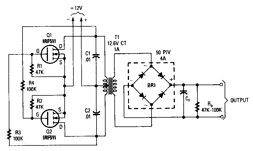
The circuit will convert 12v dc to 120v ac.
This basic inverter circuit can handle up to 1000watts supply depends the t1, t2 and transformer used. The circuit is shown in the fig. Image of the pcb layout of this high power inverter circuit diagram is given. This capacitor reduces the harmonics feedback to the source.
0 177 5 minutes read.
Line voltage, phase voltage, line current \u0026 phase current in star \u0026 delta how does an inverter work? A 12v lead acid battery can be used for powering the circuit. In this video you will learn to make a relatively simple high voltage inverter circuit. The main circuit of solar on grid inverter is presented in the following diagram.
A voltage source full bridge inverter is used at the output of the boost stage to convert the dc link voltage to sinusoidal output voltage.
Invented by heinrich greinacher in 1919 they were used in the design of a. Voltage source type inverters control the output voltage. High voltage multiplier circuit diagram. The circuit can be also used in mosquito swatter bat application by replacing the iron cored transformer with a ferrite core counterpart.
And the inverter acts as a voltage source.
The internet is flooded with single phase inverter circuit diagrams, but there are only few circuit diagrams of 3 phase inverter out there, a simplest possible 3 phase inverter is described here. The circuit diagram of three phase bridge inverter consists of minimum of 6 scr and 6 diodes. Need more voltage than your supply can deliver. Op amp 2 as an inverter.
First with a double voltage module voltage for the op amp power supply.
R2, r3, r4, r5 = 1k, t1, t2 = irf540; Based on how many turns you add to the hv secondary winding, you can. The icl7660 or max1044 can be selected. Parts list for the above explained 150 watt inverter circuit diagram:
With only 3 volts course of this series has been able to work
(see l 1 to l 3 High power 10 kv generator circuit. The following diagram is the basic design diagram of inverter circuit.