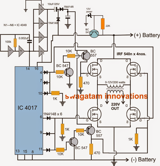
This topology can be used as inverter cells in cascaded multilevel inverters. Through the opening and closing of switches, dc power (from batteries, etc.) is inverted into ac power of a certain frequency or variable frequency, which is used to drive ac motors (asynchronous motors, etc.). This type of motor driver can control the speed as well as the direction of rotation of the motor.
(a) Structure of single phase cascaded H bridge inverter
As you see in the above figure the circuit looks like the capital letter 'h'.
If you’re not sure how the transistor works, i recommend you read the article how transistors work first.
The components required for conversion are two times more than that used in single phase half bridge inverters. Circuit containing 4 switching elements + 4 catch diodes switching elements are usually bipolar transistors or mosfets catch diodes are used to prevent short circuiting path of current controlled by switches. Circuit diagram & its working the inverter is a power electronic. Bookmark file pdf h bridge inverter circuit using ir2304 center tap transformers, and allows the use of transformers with two
These circuits are often used in robotics and other page 14/38
Control switch can be any electronic. An h bridge is a set of four switches that are assembled in such a way that an arbitrary load impedance is decoupled from a direct current (dc) power rail and ground. Control switch can be any electronic switch i.e. The circuit of a full bridge inverter consists of 4 diodes and 4 controlled switches as shown below.
The name is derived from its common schematic diagram representation, with four switching elements configured as the branches of a letter h and the load connected as the.
Hello i am designing h bridbe mosfet inverter with gate driver hcpl3120 i need help in circuit please help circuit diagram with all four drivers connected i am very confused about that please help me 8 rows what is half bridge inverter : These circuits are often used in robotics and other applications to allow dc motors to run forwards or backwards. The circuit has four switches.
In the left side of the load, two switches are connected in series and in the right side of.
Start date may 15, 2019; May 15, 2019 #1 khalil977. Sbreaks were used in order to simulate the switching characteristics of near ideal transistors. Mosfet, bjt, ijbt, or thyristor, etc.
Two major features of performing.
H bridge inverter circuit thread starter khalil977; Read book h bridge inverter circuit using ir2304grown to.


