I have used ir2210 mosfet gate driver circuit. Circuit containing 4 switching elements + 4 catch diodes switching elements are usually bipolar transistors or mosfets catch diodes are used to prevent short circuiting path of current controlled by switches. If you are driving an inductive or motor load you will need flyback or freewheel diodes across all mosfets.
MOSFET Bridge Rectifier Circuit MOSFET Hbridge Circuit
Build your own h bridge inverter at home.
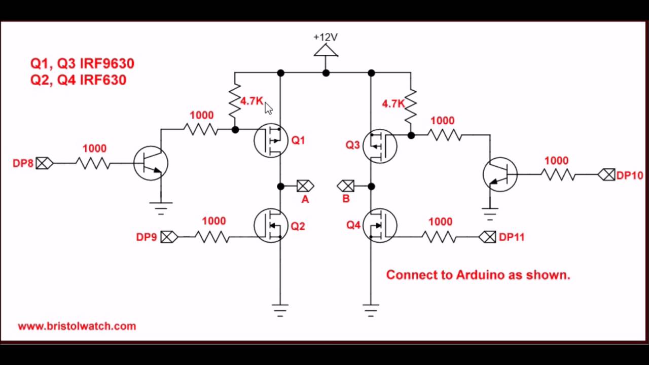
The mosfets are used as switches and are activated in diagonal pairs.
First prev 2 of 2 go to page. The voltage output is in staircase form. Now the thing is to implement full bridge using ir2110 i will need to use two of the ic's and then connect the lowside input lin of ic1(ir2110) to the the high side input hin of ic2(ir2110) so that that way diagonally they botje turn on causing current to flow but the catch here is that both inputs will receive pwm pulses( chopped 50hz pulses) so this means using. Oct 3, 2018 #21 klausst super moderator.
Awesome electronics projects using sg3525 ic and power mosfets.
In a typical h bridge configuration as shown in figure 2 there are two high side mosfets, each located on opposite sides of the bridge. These circuits are often used in robotics and other applications to allow dc motors to run in or out. So my question is, what should be done to the circuit to avoid mosfets blowing? It is the simple and elegant solution to all motor driving problems.
In order to bias these mosfets in the active region a voltage must be applied to the gate that meets the v gs(th) value as specified in that particular mosfets data sheet.
Circuit diagram of h bridge using ir2110. The dc source may be batteries, solar cells, etc. Compete circuit diagrams of h bridge are shown below. Joined apr 17, 2014 messages 21,430 helped 4,559 reputation 9,130 reaction score
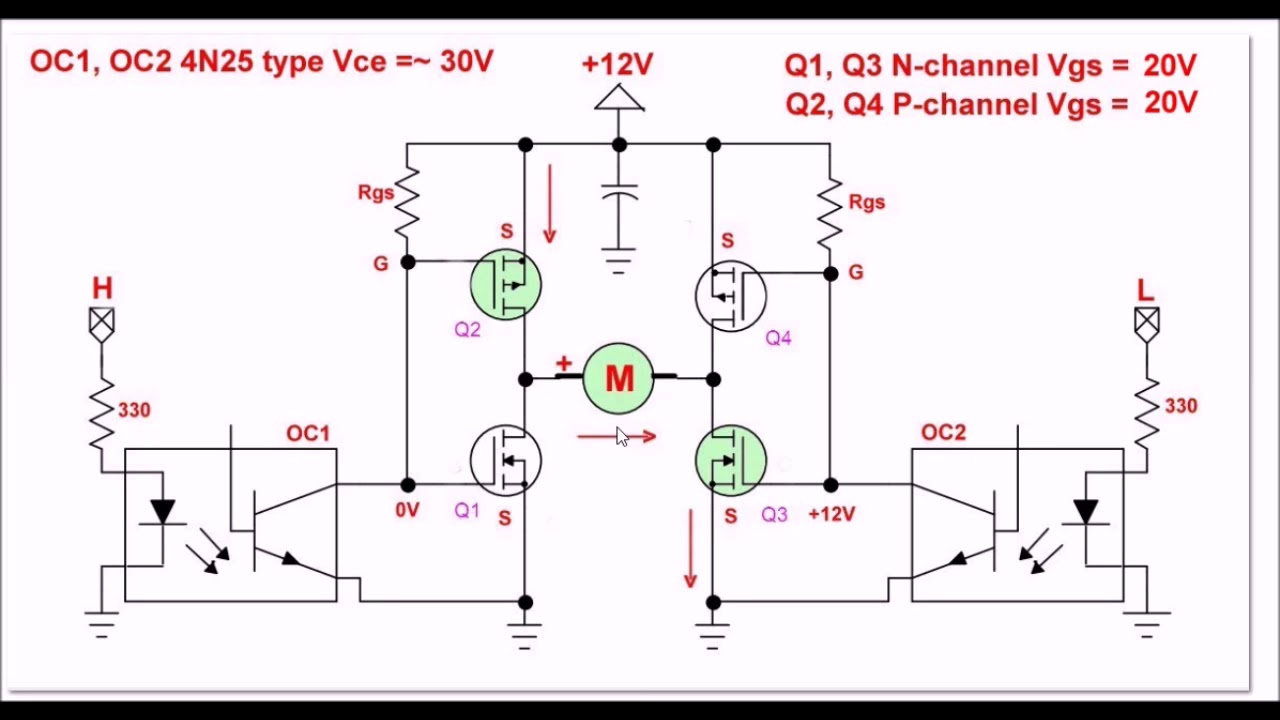
Ir2210 high and low side drivers outputs are used to drive these mosfet.
The normally closed (nc) contacts are grounded and normally open (no) contacts are connected to +12 volts. And the output of the 12v supply that i used to power the vcc pin of the ir2110 gets messed up as well. But all over sudden, two mosfets blew off, one from the high side and one from the lower side. But when i try to combine them the ir2110 always blows up.
In the circuit, we see that the 4 mosfet surrounding the motor form an “h” shape.
I have built the circuit attached herein on a pcb. A dc motor is connected between the two commons. Thus it protects the corresponding mosfet from damage. Status not open for further replies.
Although using 4 n channel inverters depend on specialized driver ics with bootstrapping , yet the efficiency overweighs the complexity, hence these types are popularly.
The diodes d1 to d4 provides a safer path for the back emf from the motor. The direction can be changed easily and the speed can be controlled. It's free to sign up and bid on jobs. In its normal state, both motor connections are grounded through the switches.
In h bridge two mosfets are used as high side mosfets and two used as a low side mosfets.
An h bridge is an electrical circuit that changes the polarity of an applied voltage to a charge. You can easily convert 220v dc to 220v ac without u. In one of our earlier articles we comprehensively learned how to build a simple arduino sine wave. Start date sep 27, 2018;