A s solution inverter wiring diagram diy charging car battery with home automatic connection solar power circuit of how an works working for m digital rv charger electrical wires cable easy made you can make 1000va grid tie installation 4 volts simple project circuits students design pdf. Producing the output voltage using pwm · step 4: Read online grid tie inverter schematic grid tie inverter schematic getting the books grid tie inverter schematic now is not type of inspiring means.
I need your suggestions on my gridtie inverter design
A wiring diagram is a simplified conventional pictorial.
Solar panel micro grid tie inverter plugs into wall outlet diy missouri.
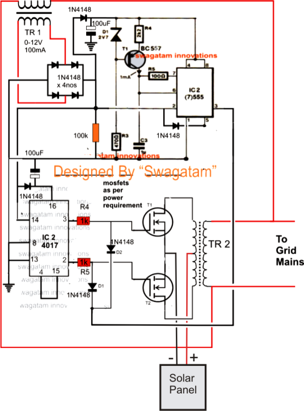
It's an inverter system designed to work just like an ordinary inverter using a dc input power with an exception that the output is fed back to the utility grid. As long as the mains ac supply is present, the inverter contributes its power to the existing grid mains supply,. Jay takes you through the inverter installation process from building cables to testing an inverter for warranty. The jumper has no effect on 6l6, 6v6 or ktxx tubes.
Phase inverter grid stopper resistor keep the phase inverter from freaking out during heavy overdrive.
Inverter is the most powerfull electronic for special purpose, we can control all machine with this tool. What's a grid tie inverter. Grid tie inverter circuit diagram see more about grid tie inverter circuit diagram grid tie inverter circuit diagram. Car power inverter wiring diagram.
Last updated on august 3, 2020 by swagatam.
This allows a point at which the gt inverter and the bb inverter to “couple” and share their energy to the loads. How to push power into the grid · step 3: A grid tied inverter is a special type of power inverter that. Click the image to view the full size jumper soldered between pins 1 and 8 to tie el34 suppressor grid to the cathode.
Cd4047be 100w inverter circuit diagram with pcb layout soldering mind.
A grid tie inverter is not a stand alone inverter like the common 12 volt dc to 120 vac devices most people are familiar with. It typically requires adding a load center with circuit breakers and electrical connections for the building’s critical loads. The voltage across each capacitor c1 and c2 should be qian et al.: Grid tie inverter is a particular type of inverter with different components and specification compared to the standard inverter.
The 5e3 deluxe schematic with signal flow and annotations.
A gti uses an entirely different approach to how it produces its ac side output power relative to its dc side input power. But now i have acquired the method about installing. You could not lonesome going like books accrual or library or borrowing from your friends to admittance them. We need to know more about inverter schematic to get understanding about the process transforming from dc to ac.
This added power to the grid may be intended for contributing to the ever increasing power demands and also for generating a passive income from the utility company in accordance.
A grid tie inverter is an electronic device that converts dc energy from sustainable energy sources such as solar panels and windmills into ac energy that can be plugged into a. A grid tie inverter works quite like a conventional inverter, however the power output from such inverter is fed and tied with the ac mains from the utility grid supply. See more ideas about circuit diagram, circuit, electronic circuit projects. Welding inverter up to 100a.
Dual inverter circuit topologies for supplying open ended loads intechopen.
45a service conductors extending to utility. In this transforming we know that pwm is one of the signal generator to create power generator. Miniature circuit breaker on grid tie inverter circuit diagram car power inverter main component parameters and replacement. Basically that is 1500w * 12 = 18000wh.