In half bridge inverter, peak voltage is half of the dc supply voltage. The circuit of a full bridge inverter consists of 4 diodes and 4 controlled switches as shown below. In one of our earlier articles we comprehensively learned how to build a simple arduino sine wave.
Free Owners Manual PDF Simplest Full Bridge H Bridge
The circuit provides a great way to understand some of the behaviors of this very important topology.
During the interval between 0 and t/2 i.e., for 0 ≤ t ≤ t/2, thyristor pair t 1 and t 2 are triggered and they start conducting.
1 shows single phase bridge inverter with resistive load. The main difference between half bridge and full bridge inverter is the maximum value of output voltage. The inverter output voltage was about 215v and frequency 50hz. Single phase full bridge inverter.
The power circuit of a single phase full bridge inverter comprises of four thyristors t1 to t4, four diodes d1 to d1 and a two wire dc input power source vs.
In full bridge inverter, peak voltage is same as the dc supply voltage. R = 200 and l = 40 mh. In a full bridge converter configuration, the dc voltage is converted to ac by switching alternatingly to reverse the polarity which connected to the load quickly. The commercial units are known for their compact size, high efficacy and decent power output.
In full bridge topology has two such legs.
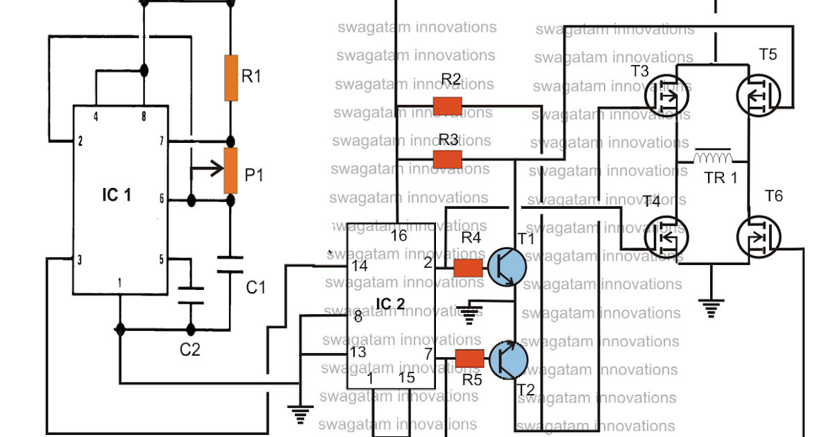
Each leg of the inverter consists of two series connected electronic switches shown within dotted lines in the figures. The output of the full bridge inverter was more The arrangement of the inverter consists of four transistor, (mosfet or igbt).to obtain an ac waveform at the output, the transistors are turned on and off in pairs of q 1, q 2 and q 3, q 4. The use of full bridge configuration
Download scientific diagram | full bridge inverter circuit from publication:
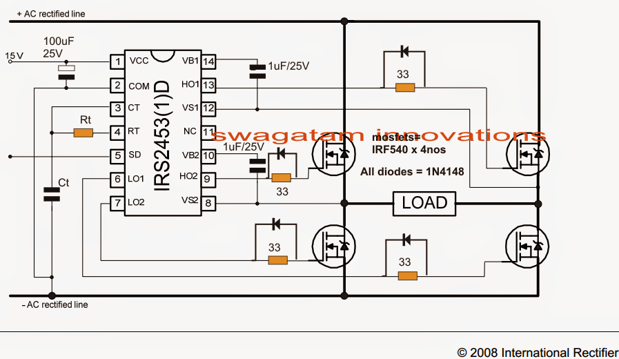
An easier method utilizing a simple mains transformer is however relatively adequate to supply. The full bridge inverter circuit basically consists of 4 feedback diodes and 4 controlled switches (like thyristor, igbt or mosfet). The full bridge inverter circuit basically consists of 4 feedback diodes and 4 controlled switches (like thyristor, igbt or mosfet). The switching frequency is 60 hz and dc input voltage vac is 150 v.
Comments (0) copies (1) full bridge inverter.
Similarly, qc and qd are switched at 50 % duty and 180 degree out of phase with each other. Adjust the value of the capacitor c1. What is the affect on the output voltage ripple? Qa and qb are switched at 50 % duty and 180 degree out of phase with each other.
Full bridge inverter figure 12 introduced the design of the full bridge inverter with the following values, (24v) battery, (50mh, 330uf) low pass filter, (24/220)v transformer.
This configuration consists of 2 pairs of switches that s1s2 and s3s4 which active alternately. Single phase half bridge inverter r load single phase half bridge inverter circuit basically consist of four thyristor (t1to t4) and four diode (d1to d4) these diodes are called feedback diode and these diodes function only when. Simply select an application and click through to the block diagram to discover our semiconductor solutions. The components required for conversion are two times more than that used in single phase half bridge inverters.
In this type of inverter, four switches are used.
The sine wave is gotten as shown in figure 14. The inverter is connected to a reactive load given by: Thus to obtain a positive voltage (+v) across the load, the. Figure 1 shows a simplified circuit of a phase shifted full bridge.
Each diode is connected in antiparallel to the thyristors viz.
Find everything you need for your next product design. No description has been provided for this circuit. The circuit is configured to provide 5v.