1000w power inverter circuit diagram: A relatively simple 1000 watt pure sine wave inverter circuit is explained here using a signal amplifier and a power transformer. 1000w 12v dc home power inverter circuit board design.
1000w Inverter Circuit Diagram Diagram Media
It is necessary to connect a fuse with the power line and always a load have to connected while power is being applied.
555 is a timer ic which is used to generate time delay.
Thanks for the way u ‘ve been solving electronics projects problems.pls, l need a working 1000w inverter circuit diagram using irf 150 mosfet. Last updated on august 3, 2020 by swagatam 241 comments. In the electronics or logic design subject, the inverter is also known as the not gate, which does nothing but logical negation.elaborating more, the inverter or not gate makes the high a low and the low a high. Make this 1kva (1000 watts) pure sine wave inverter circuit.
The home inverter overall structure is, downside is a large cooling plate, upside is a power board with same size as the cooling plate, length 228mm, width.
This is the power inverter circuit based mosfet rfp50n06. You may add some mosfets with parallel… read more » As can be seen in the first diagram below, the configuration is a simple mosfet based designed for amplifying. The project is based on the low cost egs002 spwm driver board module.
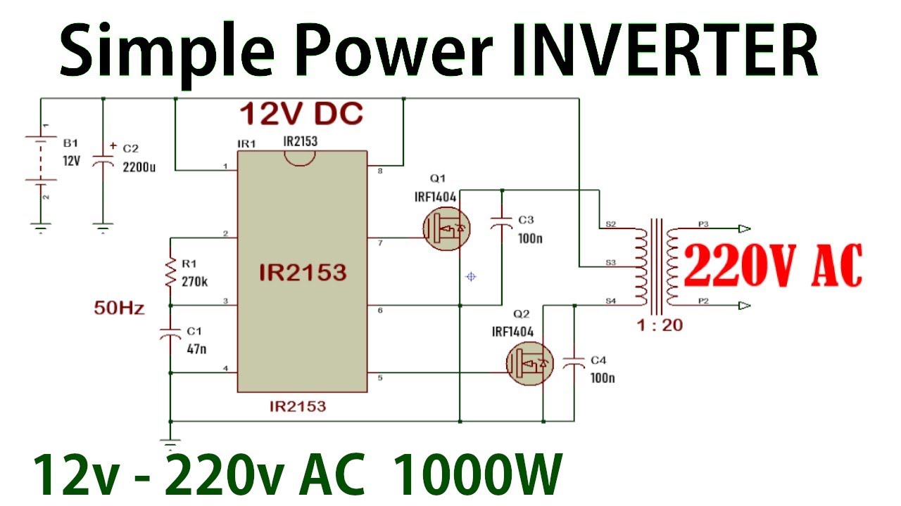
How to do 12vdc to 220vac inverter circuit 1000w.
To participate you need to. 1000w power inverter circuit diagram: How to make a simple solar inverter circuit homemade projects. December 29, 2019 at 5:53 pm.
Home decorating style 2022 for inverter circuit diagram 12v 1000w, you can see inverter circuit diagram 12v 1000w and more pictures for home interior designing 2022 317341 at.
I need the 1000w inverter circuit diagram which is economical in terms of cost,. Heatsink is required for cooling the mosfets. Bookmark file pdf 1000w power inverter circuit diagram mylikeore 1000w power inverter circuit diagram mylikeore | f5f62de5a9ca1d075e462b4a364a5488 This 1000 watt power inverter circuit diagram based on mosfet rf50n06.if you want more power then add additional mosfet paralleled at rf50n06.this mosfets are 60 volts and 50 amps as rated.
The rfp50n06 fets are rated at 50 amps and 60 volts.
This inverter is designed to power about 2200 watt, the headline of this paper is 2000 watt is because the dc power supply maximum output current is 100a, so gohz tested it at 2000 watt, for more than 12 hours testing, it can work well at 2000 watt, there. This is the power inverter circuit based mosfet rfp50n06. Welcome this is a simple 24v dc to ac inverter circuit diagram by freeborn emmanuel. We have so many collections wire wiring diagrams and schematics, possibly including what is you need, such as a discussion of the inverter circuit diagram.
Click here to register now.
Diy cheap 1000w pure sine wave inverter (12v to 110v/220v): This power inverter is designed for 12v dc, but also can be connected to 24v dc, my goal is 800 watt, strive to 1000 watt pure sine wave output. Use it to run the mortor if. Electro tech is an online community (with over 170,000 members) who enjoy talking about and building electronic circuits, projects and gadgets.
100 watt inverter circuit diagram ups diagrams pdf free solar power 1000w schematic manual digital 3 easy sg3525 circuits explored page 2 supply homemade 2000w with china 667 l19y21 14 sch 500 battery mlt019l c megmeet آمن بحيرة تيتيكاكا تمييزي kayal factory 12v 6 m dc to 240v electronic.
Diagram using full transistor c945 or c1815. The inverter capable to handle loads up to 1000w, it’s depended on your power inverter transformer. The inverter is a transformer base and not chopper or circuit base inverter and the transformer winding is a home made transformer winding formula which i have been using for any inverter winding, if i should start explainning how i wind the transformer it will take a longer time but if you have enough time to experiment this simple. Can someone sent me a 1000w 12v dc to 220v ac circuit diagram with a frequency of 50hz, the circuit diagram should be practical so that i can try it in the laboratory.
Hi, if possible in future we will post a project!
Car batteries for powering you home? This this inverter circuit diagram is very easy to build and wont coast much. The rfp50n06 fets are rated at 50 amps and 60 volts. This power inverter has a good starting ability, it only takes about 1 second for two parallel 1000 watt solar lamps.
The diy inverter board can handle up to 1kw (depending the transfor…
Before jumping into the inverter circuit diagram, it is necessary to know the logical symbol of the power inverter. The circuit built based ic cd4047 to generate sine wave signal 50hz and then the power transistor 2n3055 will boost the signal so that the signal have high power high electric current.