R2, r3, r4, r5 = 1k, t1, t2 = irf540; Remember these are all generalities, there are many valid reasons to make exceptions. With this kind of an illustrative guidebook, you’ll have the ability to troubleshoot, prevent, and total your tasks without difficulty.
How to build 200W inverter circuit Diagram project
As a result, it makes it easy for you to catch them without any struggle whatsoever.
The icl7660 or max1044 can be selected.
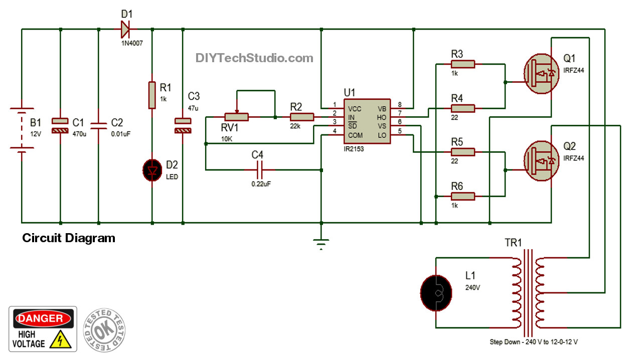
The picture above is our inverter schematic. This time we used the larger power transistor 2n3055, and only two resistors are used, and the power of the resistor is selected to be larger, so the output power of the circuit will be corresponding. You may use the universal board and connect the battery to input. The circuit will convert 12v dc to 120v ac.
This is based on the mosfet3205.
Op amp 2 as an inverter. Inverter circuits are among the easiest circuits to build for newbies. (the general power transformer) then, bring the 2n3055 transistor to screw at the large heat sink. R1 = 220k pot, needs to be set for acquiring the desired frequency output.
This electric current shocks the fish and leaves the fish in an unconscious state.
This is the circuit diagram of 2000w high power inverter circuit. This basic inverter circuit can handle up to 1000watts supply depends the t1, t2 and transformer used. Please careful with this circuit. They are also called power inverters.
First with a double voltage module voltage for the op amp power supply.
The following diagram is the basic design diagram of inverter circuit. The spwm accuracy of eg8010 was not high enough waveform, so the inverter output was not good enough as pure sine wave. The circuit is simple low cost and can be even assembled on a veroboard. Op amp 1 generates a 50 hz sine wave as the reference signal.
C1 = 0.01uf, c3 = 0.1uf;
Parts list for the above explained 150 watt inverter circuit diagram: It’s designed to kill fish by delivering an electric shock. The above figure uses a 1w 400 ohm resistor. There are many basic electrical circuits for the power.
Look at the circuit diagram above.