5kva ferrite core inverter circuit full working diagram with calculation details homemade projects. Npri = vin * 10^8 / 4 * f * bmax * ac Inverter connection to db help needed inverters power forum renewable energy discussion.
Microtek Inverter Circuit Diagram Compact, Ferrite Core
7 simple inverter circuits you can build at home homemade circuit projects.
Moreover, there is another benefit of soft ferrite cores, that is, they can change the magnetic.
Ferrite core is a type of magnetic core made of ferrite on which the winding of electric transformer and Here we are going to used special integrated circuit for high frequency name as ic sg3525 for two purposes. Moreover i was referring to a good quality iron core inverter not a ferrite core one…and also a single piece will always cost you 5 to 10 times more than when you buy the same in bulk. And, hence they are ideal to make them, magnets, etc.
Lg ac wiring diagram fully4world electrical wiring diagram thermostat wiring electrical circuit diagram sir i need to connect an 05 kw inverter in my home to run 2 tube lights and 2 fans.
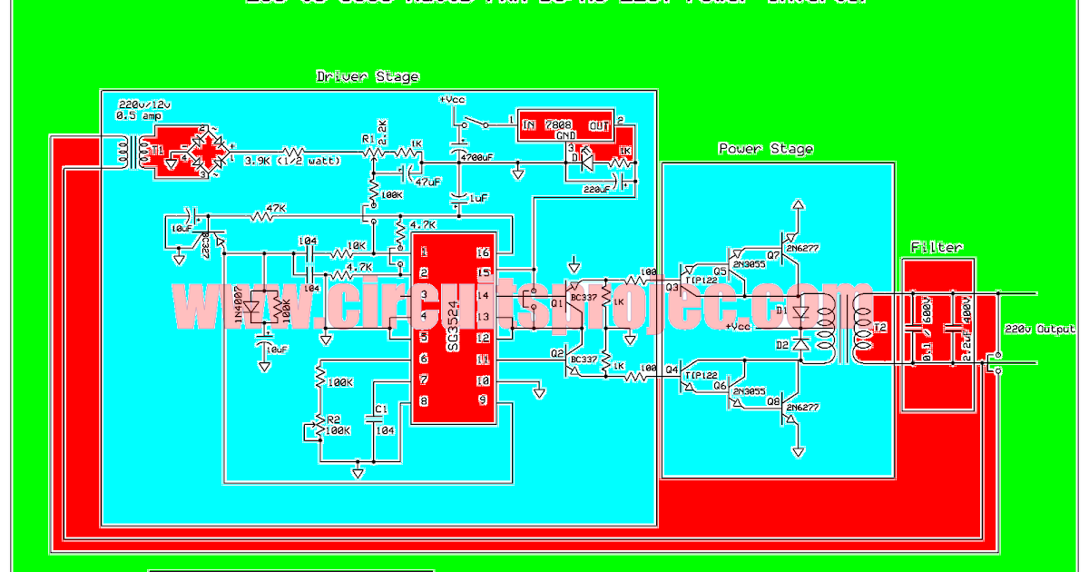
See more ideas about circuit diagram, circuit, electronic circuit projects. Using 5 sealed lead acid batteries of 12v 10ah; We are going to make a high frequency ferrite core transformer based inverter circuit which can output 500 watt 220vac at 50hz with good efficiency. But we need to calculate primary turns to find secondary turn of ferrite core transformer.
After calculation of battery voltage we have 66volts at 10 amps when full charged.
Formula to calculate primary turns for ferrite core transformer is given below: You 'll see it, working with batteries and. It can be used with battery. Charging the batteries from ac shore line or ac.
We will learn how a ferrite core inverter functions stage by stage extensively.
My suggestion would be to use ferrite core transformer based Next comes the supply power to ic2153. Rvs have a battery bank which is used to power the rv appliances. 5kva ferrite core inverter circuit preparation details:
Inverter design using high frequency chandrakant r shinde1, gopal r shinde2,.
Calculating a ferrite core transformer is actually quite simple, if you have all the specified parameters in hand. We have three know variables like turns ratio which can be calculated by above equation, input voltage and output voltage. If we compare both then the soft ferrite cores have a higher coercivity than the high ferrite core. 5kva ferrite core inverter circuit full working diagram with.
Inverter home wiring diagram pdf.
Total voltage = 60v actual voltage = 66v fullcharge(13.2v each batt)voltage = 69v trickle level charge voltage. The problem is with the ferrite core inverter, if it produces only 120v (squarewave) at output, the rectified output will also be 120vdc, because for squarewave 120vac the rms is equal to 120v. Transformerless inverter circuits circuit 1000 watt modified sine wave switching dc ac 12v make your own full homemade 2000w power with 5kva ferrite core 2kva all about simple sinewave self charging off grid pure 1kva diagram solar 5000w 48v pwm based on sg3524 inverters 500w to 220v tied if a higher. The ferrite core comes up with basic two types, hard ferrite core, and soft ferrite core.
220 volt ac output sinus inverter circuit built on sg3525 smps control integrator transformer used in transformer computer power supply (ferrite core e type) the input voltage of the inverter circuit is between dc 10.5 volt and 14.5 volt.
Aug 03, 2020 · a relatively simple 1000 watt pure sine wave inverter circuit is explained here using a signal amplifier and a power transformer. You need a ferrite core inverter that produce 220v rms, one such inverter is shown in this post: When the input voltage drops and over load warnings are given with buzer and led 220v output voltage,. How to calculate ferrite core inverter transformer.
In this video, i'll show you circuit diagram of my smps (switch mode power supply) based inverter and explain it.
But only few of them try patiently and make a pure sine wave inverter, that’s because the complexity involved in the construction of the circuit. Ferrite core inverter circuit diagram.