Cat6 cables have a bandwidth of 10 gbps at 250 mhz, while cat5e can only reach a gigabit per second, enabling cat6 cables to carry more data. The cat 5 wiring diagram rj45. Contact now click for details.
Custom_CiscoRJ45toDB9_ConsoleCable_WiringPinout Flickr
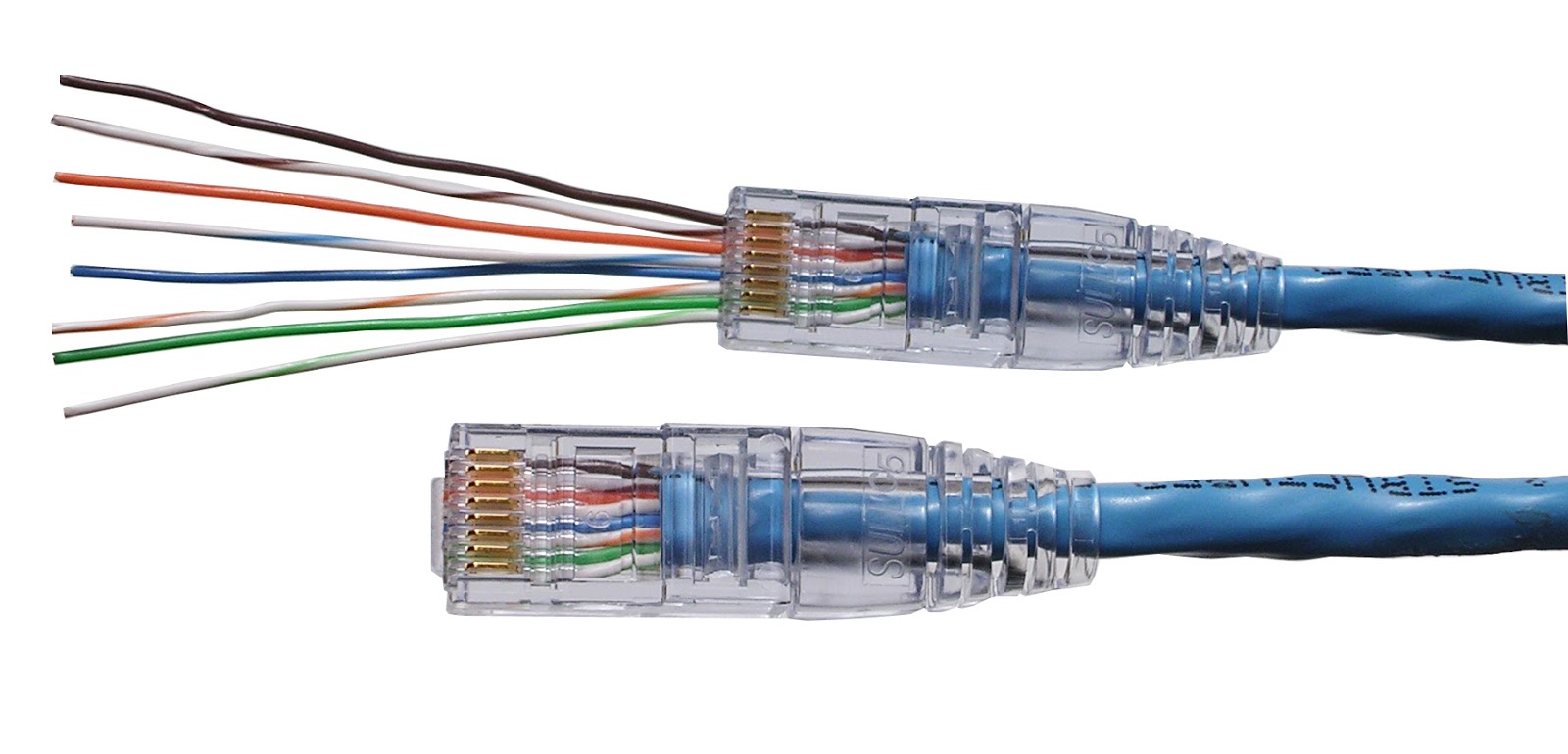
The image at right shows how to hand wire a commercial rj45 connector for use with an ethernet based network.
Pin 1 → white and green (transmit +) wire;
Brown & white pin 8: Run the full length of ethernet cable in place, from endpoint to endpoint, making sure to leave excess. Utp (unshielded twisted pair) cables come in several variants, including cat6, cat5e, and cat5. Law | published june 18, 2021 | full size is 950 × 1267 pixels.
An ethernet cable can be broken down into two main parts:
Pin 8 → brown wire. There are two standard rj45 pinouts for the individual arrangement of the wire connections to the rj45 connectors within an ethernet cable: Green & white pin 4: An rj45 connector is a modular 8 position, 8 pin connector used for terminating cat5e patch cable or cat6 cable.
Remember that each of these cable designs operates with 4 twisted pairs, or eight wires, hence the necessity of rj45 connectors with 8 pins to connect all those wires.
Although there are 4 pairs of wires, 10baset/100baset ethernet uses only 2 pairs: This is the option shown in most home wiring videos on youtube. Rj45 ethernet cable wiring diagram perfect cat 5e ethernet. Rj45 ethernet cables / networking cables are available at mouser electronics.
There are two main options as shown in the schematic above.
Pin 1, 2, 3, 6 for data, pin 4, 5, 7, 8 for poe power supply. Orange & white pin 2: The ethernet cable used to wire a rj45 connector of network interface card to a hub, switch or network outlet. Mouser offers inventory, pricing, & datasheets for rj45 ethernet cables / networking cables.
How to wire fixed ethernet cables:
The wiring diagram is shown with the hook clip on the underside. Rj stands for “registered jack” and 45 refers to the interface standard number. The hook would be on the back of the image as displayed. Rj45 wire order white with orange stripe.
Steps for making an rj45 connection.
The jack should have a wiring diagram or designated pin. It is the more common standard used when cabling for businesses. Registered jack standard number 45 specifies the amount of wires in the cable, the order in which they appear, and the usage of the 8p8c physical connector. One or other of the conventions should be followed, as this will ensure the required connectivity, although as it is just a colour convention and the same wires and pairs are connected to the same pins, it does.
All cat5, cat5e, cat6, cat6a, cat7, and cat7a cables use the same rj45 connectors.
Pin 3 → white and orange (receive +) wire; Specifically, rj45 defines two wiring standards: T568b is the standard followed by the majority of ethernet installations in the united states for rj45 color code. Oldest 10mbit ( ethernet ), old but still used 100mbit ( fast ethernet ), modern 1gbit ( gigabit ethernet) or newest 10gbit.
It might resemble a telephone jack, however, it is a bit wider.
Below is a description of the basic functionality of each wire associated with the ethernet port pins on your camera: Pin 5 → white and blue wire; The t568a and t568b standards. There are two standards recognized by ansi, tia and eia for wiring ethernet cables.
90 degree rj45 connector this customized ethernet cable designed and processed all by customer requirement designed by short and 90degree ethernet cable wiring offered for cat5 and cat6 by utp stp ftp the db rj series in different pins and gender.
It’s got a spot for eight pins, which means that it contains eight separate wires. • another way of remembering the colour coding is to. Rj45 is the most common type of the connector that is being used for ethernet networking. Use the rj45 crimping tool to remove the wire insulation of the ethernet cable 2.5 cm from the end then unwind the wires inside.
Pin 4 → blue wire;
At one end, cut the wire to length leaving enough length to work, but not too much excess. Pin 7 → white and brown wire; A pinout is a specific arrangement of wires that dictates how the connector is terminated. The other option is to use several switches perhaps one per floor and wire those switches back to a central location.
Ethernet cable pinout t568a and t568b rj45 pinout for a lan cable.
Repeat the above steps for the second rj45 plug. Insert each wire into the rj45 connector in the below order. Strip off about 2 inches of the ethernet cable sheath. The wall jack may be wired in a different sequence because the wires may be crossed inside the jack.
It also defines the design and dimensions of the clear plastic plug that terminates the cable.
Purple & white pin 6: It is the more common standard used when cabling for businesses. A utp cable and an rj45 header connector.


![[FK_1034] T1 Crossover Cable Pinout Diagram Also T1 Rj45](https://i2.wp.com/static-assets.imageservice.cloud/392017/cat-5-cable-color-code-diagram-as-well-rj45-wall-jack-wiring-diagram.jpg)
