For general purpose electronics work, the multimeter reigns. An attenuator in input stage to select the proper The resistor r1 and capacitor c1 are used to set the internal oscillator (clock) frequency at 48hz, clock rate at which there will be three readings per second.
Digital multimeter circuit using ICL7107
The combination of a resistor in series with pmmc galvanometer is a dc voltmeter.
I'm looking for the internal circuit diagram of dt830x (or dt830d).
They are dc voltage, ac voltage, dc current, ac current, and resistance. So the additional block to the diagram of figure, to act as a panel meter to measure alternating voltage is a.c to d.c. Internal adc of this ic reads the voltage that to be measured and compare it with an internal reference voltage and converts that into the digital equivalent. It is provided with inbuilt power supply necessary for the functioning of the device.
For example, measure dc voltage, acv, dc amp meter, ac amp meter and as the ohms meter, etc.
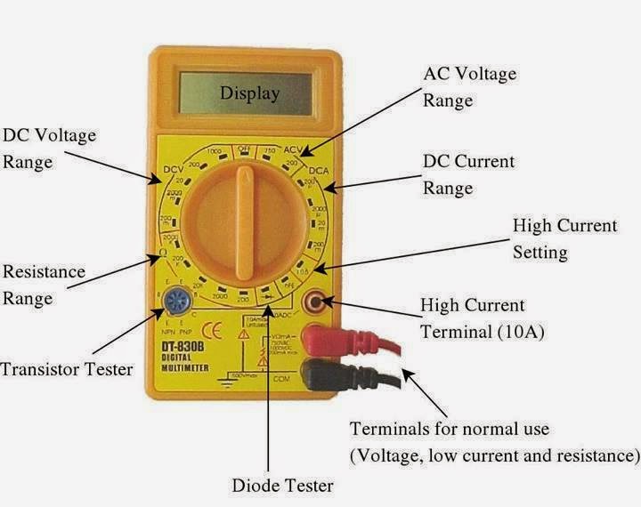
Electronic multimeters it is one of the most versatile general purpose instruments capable of measuring dc and ac voltages as well as current and resistances. Digital multimeters convert analog signals to digital information. The multimeter diagram is shown above that includes three parts like display, knob, and ports. Most modern multimeters are digital.
The above circuit looks like a multi range dc voltmeter.
In addition it must have a provision for measurement of resistance also. A digital multimeter is one that is capable of measuring voltage, current, of alternating current circuits as well as direct current circuits. The basic block diagram of a typical digital multimeter is given in the diagram below. We modify them from a normal dc digital voltage meter circuit to smart multimeter.
The schematics do not show placement or scale, merely function and flow.
On account of developments in the integrated circuit (ic) technology, it has been possible to reduce the size, power requirements and cost of digital voltmeters.in fact, for the same accuracy, a digital voltmeter now is less costly than its analog counterpart. A digital multimeter (dmm) is a measuring instrument used to measure various electrical quantities. The part of the circuit diagram of multimeter, which can be used to measure dc voltage is shown in below figure. Digital panel meter block diagram.
Digital multimeter is a test equipment which offers several electronic measurement task in one tool.
Circuit diagram and working explanation: A digital voltmeter is a versatile and accurate voltmeter which has many laboratory applications. Posted on may 19, 2014 by electronic products. Digital voltmeter is a voltage sensitive device.it measures ac or dc voltage and displays the value directly in numeric form instead of pointer deflection.
There exist many factors that affect the measurement accuracy of a digital voltmeter(dvm).
The function of the meter can be changed by switching the dial. In general, dmms have a minimum of five typical functions. The block diagrams for measuring steady voltage, and alternating voltage are shown above : Led digital voltmeter circuit diagram with ic7107.
The 200 mv module is shown only as a single block.
The standard measurements that are performed by a dmm are current, voltage and resistance. Digital multimeter circuit using icl7107. While specifications vary, most dmms can be described with block. Block diagram of a dmm using successive approximation register adc.
Digital multimeter block diagram explanation.
An analog meter (figure a) moves a needle along a scale. As shown in the block diagram, in a typical digital multimeter the input signal i.e ac or dc voltage, current, resistance, temperature, or any other parameter is converted to dc voltage within the range of the adc. The multimeter name is given to it to define its ability to measure multiple quantities. Working principle of digital multimeter.
The standard and basic measurements performed by multimeter are the measurements of amps, volts, and ohms.
Although different dmms will use different circuits, the same basic techniques tend to be used from one test instrument to the next. Then only it becomes the digital avo meter. It's a simple multimeter capable of accomplishing varied measurements. Apart from these, a digital multimeter can also measure temperature, frequency, capacitance, continuity, transistor gains etc.
Dt9205a digital multimeter circuit diagram :
Also, note the small triangular symbol representing the instrument ground. It is also known as the voltmeter or ohm meter or volt ohm meter. Working of this digital voltmeter circuit is very simple. Dvm is an acronym for digital voltmeter.dvm was first invented in 1954 by andrew kay.
Multimeter is a measuring instrument.
The electronic multimeter is a device which is used for the measurement of various electrical and electronic quantities such as current, voltage, resistance etc. Generally, the display on the multimeter includes 4 digits which display a negative sign. The block diagram of 7107 and that of. It is so versatile available function.
Electronic voltmeter circuit diagram (block diagram) note the large triangular graphic symbol normally used to represent an amplifier.
I am showing you a digital multimeter circuit using icl7107. The voltage intended to measure is fed to the circuit through resistors and capacitors as shown in the figure. The input attenuator is simply a voltage divider that divides (or attenuates) high input voltages to measurable levels. A balanced bridge dc amplifier and a pmmc meter.
From this, the actual workings of a piece of electronic equipment can be determined.
It can be used to measure voltage, current and resistance. It is also called electronic multimeter or voltage ohm meter (vom). Schematic diagram dt9205a digital multimeter: The following figure represents the digital multimeter block diagram with all the functional blocks.
Analog multimeter shown in the figure is cheap but difficult for beginners to read accurately.
Electronic diagrams & schematics 6 examples of electronic schematic diagrams electronic schematics use symbols for each component found in an electrical circuit, no matter how small. Dt9205a based digital multimeter schematic:


