A multimeter can be used to measure electrical functions such as voltage, current, resistance, continuity and some are able to measure electrical frequency. Supply voltage level detector circuit 2. Functional block diagram of digital frequency meter contents show working principle of digital frequency meter applications of digital frequency meter working principle of digital frequency meter 1.
Circuit diagram of the Digital Multimeter (DMM) Download
Its block diagram is shown in figure.
The basic circuit of one type of analog electronic voltmeter is illustrated in figure 1.
This adc unit basically distinguishes between various types of digital voltmeters which we will discuss later. The block diagram of 7107 and that of the panel meter are given above to present a clear picture of panel meter, which uses the d.v.m module. The part of the circuit diagram of multimeter, which can be used to measure dc voltage is shown in below figure. And next to this signal is processed onto the pulse generator which generates a train of rectangular pulses by using both analog and digital techniques.
A digital voltmeter (dvm) displays the value of a.c.
A counter section is also employed in the circuitry that is usually a decade counter. Digital panel meter block diagram the block diagrams for measuring steady voltage, and alternating voltage are shown above : Now let us discuss how does a digital voltmeter work and working principle of digital voltmeters and block diagram. An input attenuator, an electronic amplifier, and an electromechanical voltmeter stage.
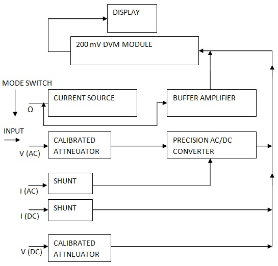
For a digital multimeter you would need to identify all the functional blocks and then indicate how they are interconnected, to achieve the system function.
Electronic voltmeter circuit diagram (block diagram) Circuit or block diagram of digital voltmeters: Numerical readout of dvms is advantageous since it eliminates observational errors. It is basically the signal i.e.
See led vu meter using transistor is analog circuit to show the level of power audio signal.
Basically i need something to show me how it works and all the different parts inside of the meter. • the function switch dial is turned to select the meter’s function. It is also called electronic multimeter or voltage ohm meter (vom). The unknown frequency signal is fed to the schmitt trigger.
Three phase meter connection 3 phase energy meter connection singele phase db wiring diagram.
The combination of a resistor in series with pmmc galvanometer is a dc voltmeter. The signal may be amplified before being applied to schmitt trigger. From the above block diagram, the voltage to be measured is given to the input signal present in the circuit diagram. The standard measurements that are performed by a dmm are current, voltage and resistance.
There are two main types of multimeters.
Or d.c voltage being measured directly as discrete numerals in the decimal number. Apart from these, a digital multimeter can also measure temperature, frequency, capacitance, continuity, transistor gains etc. The figure below shows the block diagram of a typical digital voltmeter. In a schmitt trigger, the signal is.
Block diagram of the transmitter system the schematic diagram of.
A balanced bridge dc amplifier and a pmmc meter. Digital tachometer working principle technique employed in measuring the speed of a rotating shaft is similar to the technique used in a conventional frequency counter, except that the selection of the gate period is in accordance with the rpm calibration. Digital multimeter layout • the top portion of the meter contains the digital readout area which displays the measurement value. This particular circuit is made up of three stages:
Electronic multimeters it is one of the most versatile general purpose instruments capable of measuring dc and ac voltages as well as current and resistances.
The above circuit looks like a multi range dc voltmeter. Its block diagram is shown in figure. A block diagram is a system description using a subset of functional blocks. The unknown voltage is applied to the input of the integrator, an output voltage (eo) starts to rise.
So, it can be used to measure dc.
It uses digital, analog or both techniques to generate a rectangular pulse. Below the digital readout is a black dial, called the function switch. The slope of the output voltage (eo) is determined by the value of input voltage (ei). Draw labelled diagram of cathode ray tube and explain function of each electrode in it?
Firstly dc input voltage is converted into ac voltage by chopper modulator and then it is supplied to an ac amplifier, i output of amplifier is then demodulated to a dc voltage proportional to the original input voltage.
I was hopeing someone on here might have a clue as to what goes on inside or knows of a book with a diagram in. An attenuator in input stage to select the proper The 200 mv module is shown only as a single block. Here is the working principle of integrating type digital voltmeter (dvm).
A multimeter, shown in figure 1, is a device used to measure two or more electrical quantities.
Ive been searching for a block diagram of a digital multimeter. The basic block diagram of a typical integrating type digital voltmeter ( dvm) is shown in the above figure. Draw circuit diagram of time base generator and explain its. Draw block diagram of cro and explain function of each block?
A digital multimeter (dmm) is a measuring instrument used to measure various electrical quantities.
Chopper type dc amplifier is used in highly sensitive dc electronic voltmeters. The energy is the total power consumed and utilised by the load at a. As we can see, the block diagram consists of attenuator with an analogue to digital converter after it. Explanation of various blocks input signal:
Actually it is a voltage source.
Let us assume, that the rpm of a rotating shaft is r.