The electronic block diagrams solution for conceptdraw diagram includes a set of diagrams samples and a large number of specialized electronic and electrical symbols of electronic blocks, amplifiers, pulses, repeaters, converters, waveforms, electric filters, delay elements, etc. With a neat block diagram, explain the principle of working of electronic energy meter. Let us assume, that the rpm of a rotating shaft is r.
Digital Frequency Meter Circuit Diagram and Working
There is an iron cored coil pivoted on two jeweled bearings.
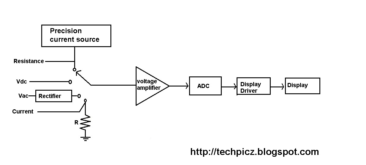
We use a rectifier to measure an ac voltage or current with the multimeter.
The coil is wound on an aluminum former or bobbin. Digital multimeter layout • the top portion of the meter contains the digital readout area which displays the measurement value. There two types of digital multimeters (dmm): The signal may be amplified before being applied to schmitt trigger.
• the function switch dial is turned to select the meter’s function.
The trivector meter gets input supply to be measured through current and potential transformers (ct and pt). The multimeter basically consists of a bridge dc amplifier, rectifier, pmmc meter, function switch, internal battery and an attenuator. And this coil is free to rotate in the field of a permanent magnet. An aluminum pointer is attached to the coil and bobbin.
Working principle of digital voltmeters:
And next to this signal is processed onto the pulse generator which generates a train of rectangular pulses by using both analog and digital techniques. Electronic voltmeter circuit diagram (block diagram) Digital multimeter is a test equipment which offers several electronic measurement task in one tool. An attenuator in input stage to select the proper
The oscillator output reaches the current to voltage converter through a selectable source resistance r s and the component under test (dut).
Principle of working of electronic energy meter (with block diagram), extra features offered by present day meters and their significance in billing. The block diagram of a smart electricity meter can be used to understand their operation and the challenges of their electronic circuit design. It consists of a 1 khz oscillator and a current to voltage converter, it is nothing but an operational amplifier. A multimeter is a permanent magnet moving coil galvanometer.
That is it gets current input through a ct and voltage input tluough a pt.
From the above block diagram, the voltage to be measured is given to the input signal present in the circuit diagram. The basic circuit of one type of analog electronic voltmeter is illustrated in figure 1. As shown in the block diagram, in a typical digital multimeter the input signal i.e ac or dc voltage, current, resistance, temperature, or any other parameter is converted to dc voltage within the range of the adc. An input attenuator, an electronic amplifier, and an electromechanical voltmeter stage.
1 shows the simple block diagram of a digital trivector meter.
For providing ac excitation, the oscillator is used in the circuit. Working principle of digital multimeter. A balanced bridge dc amplifier and a pmmc meter. Meter is shown in figure.
Here we are using two switches namely s 1 and s 2 to select the desired meter.
The measurement of dc quantities will be done by exciting the bridge with dc voltage. 1 functional block diagram of digital frequency meter working principle of digital frequency meter. The block diagram of a digital l.c.r. The standard and basic measurements performed by multimeter are the measurements of amps, volts, and ohms.
Below the digital readout is a black dial, called the function switch.
Smart meter technology circuit design. Here below we are showing a basic block diagram of an analog multimeter. The unknown frequency signal is fed to the schmitt trigger. For showing various measurements, a lcd display is used.
Block diagram of trivector meter.
This particular circuit is made up of three stages: On the contrary, the ac measurements require excitation of the wheatstone bridge with ac signal. Construction | working principle of multimeter. The function of the attenuator is that it helps to select a particular range of voltage values.
All symbols are highly simple and common for electronics.
It is also known as the voltmeter or ohm meter or volt ohm meter. Digital tachometer working principle technique employed in measuring the speed of a rotating shaft is similar to the technique used in a conventional frequency counter, except that the selection of the gate period is in accordance with the rpm calibration. The rectifier is essential in a multimeter for the conversion of ac voltage into dc voltage. When working with the scalable digital multimeter you need to have an idea of the value of voltage, current, or resistance that you are attempting to measure.
The output of the current to.
Electronic multimeters it is one of the most versatile general purpose instruments capable of measuring dc and ac voltages as well as current and resistances. The above block diagram clearly defines the connection diagram of the lcr meter.


