You may acquire a variable range of output pulse at pin 10 q and pin 11 q’ pins by adjusting the value of. Parts list for the above explained 150 watt inverter circuit diagram: Image of the pcb layout of this high power inverter circuit diagram is given.
Make This 1KVA (1000 watts) Pure Sine Wave Inverter
R1 = 220k pot, needs to be set for acquiring the desired frequency output.
Find the besttemplates at vincegray2014.
Basic schematic for dc to ac inverter scientific diagram. Power inverters have numerous applications in power electronics field. It is used in various applications like induction heating, ups, controlling electric motors, refrigerators, solar and. They can convert 12vdc from battery to 220vac or 120vac to apply small light bulbs or lamps max 10 watts.
Microtek inverter circuit diagram pdf electrical learner.
You do not have it now. Please careful with this circuit. It is necessary to connect a fuse with the power line and always a load have to connected while power is being applied. Rv power inverter wiring diagram free download 2022 by easter.gleason.
Thus to obtain a positive voltage (+v) across the load, the transistors q 1 and q.
It is hard to find equipment. They are also called power inverters. Use 24v dc supply for operation and connect 24v 5a or more than 5a transformer. This is the circuit diagram of high power 1250va digital inverter with charger.
A diagram shows how to properly wire a charge controller and an inverter into the same battery based pv system.
Few days ago, gohz made a 24v 2000w power inverter in home, sharing some design schematics and circuit diagrams. For more information visit my youtube channel “electrical learner” i am upload full video about luminous inverter repair and don’t forget subscribe my. This is based on the mosfet3205. This is the circuit diagram of 2000w high power inverter circuit.
The spwm accuracy of eg8010 was not high enough waveform, so the inverter output was not good enough as pure sine wave.
The enphase wiring diagram is here. Today i am give luminous inverter circuit diagram, ‘mosfet’ drive voltage, ‘mosfet’ driver ic number with gate voltage. The rfp50n06 fets are rated at 50 amps and 60 volts. Pins 10 and 11 are used to collect the output.
Circuit diagram for the inverter dc to ac scientific.
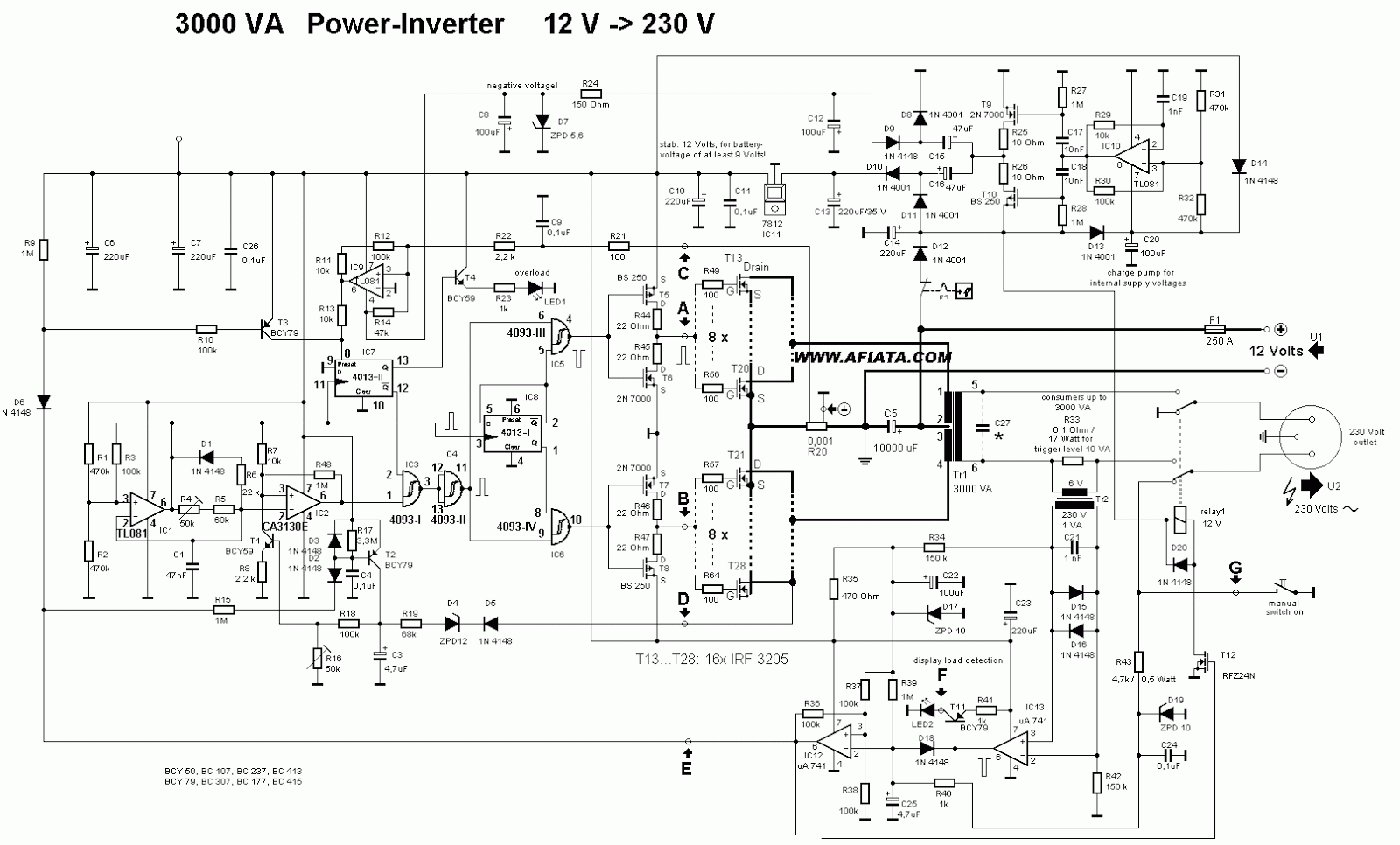
12v dc to 220v ac inverter circuit pcb. In the two circuit diagram below, just use 2 transistor, 2 resistors, and one transformer only. The cd 4047 ic is configured in this 12 volt to 220 volt inverter with the aid of several components like the potentiometer, capacitors, and resistors. Ups inverter diagrams pdf free 3000w power 12v to 230v digital circuit diagram 4 simple uninterruptible supply sinewave using pic16f72 homemade solar m 100 watt offline engineering projects electronic abc home facebook sine wave build 200w 500 with battery circuits 2000w homage schematic microtek how an works.
1 shows single phase bridge inverter with resistive load.
1000w power inverter circuit diagram: This 1000 watt power inverter circuit diagram based on mosfet rf50n06.if you want more power then add additional mosfet paralleled at rf50n06.this mosfets are 60 volts and 50 amps as rated. Inverters are devices that convert dc input supply to ac (alternating current). C1 = 0.01uf, c3 = 0.1uf;
The dead zone time was a bit.
Dc ac inverter circuit 2 the wind energy system microsources of wt scientific diagram. R2, r3, r4, r5 = 1k, t1, t2 = irf540; Switching transformerless dc ac 12v 230v 150w modified sine wave inverter. Heatsink is required for cooling the mosfets.
1 the junction box at the pv array wiring from pv array to the disconnect switch on the house the disconnect switch the wiring from the disconnect switch to the circuit breaker panel.
Luminous eco volt+ 800va/900va circuit diagram in pdf. If you think that this circuit is not good enough. The circuit of this inverter is dissimilar when compared to the commonly used inverters as it does not have involvement of a separate oscillator circuit to power up the fitted transistors. Also 500w inverter circuit for you.
The inverter capable to handle loads up to 1000w, it’s depended on your power inverter transformer.


